
Wang HongTao
Information Engineering School, Communication University of China, 100018, China
Information Technology Journal
Year: 2014 | Volume: 13 | Issue: 2 | Page No.: 310-317


ABSTRACT
The factors which affect HD camera shooting are divided into lens factors and camcorder factors. Key technical indicators of the camera in the photoelectric conversion and processing are studied. The measurement environment is designed according to the actual conditions. In practice, the measurement is divided into subjective evaluation and objective measurement. This study focuses on the objective aspect and explores the general measurement method of the HD camera through the analysis of the measurement data.
PDF Abstract XML References Citation
Received: May 06, 2013;
Accepted: July 19, 2013;
Published: February 07, 2014
How to cite this article
Wang HongTao, 2014. Research on HD Camera Technical Indicators and Measurement Method. Information Technology Journal, 13: 310-317.
DOI: 10.3923/itj.2014.310.317
URL: https://scialert.net/abstract/?doi=itj.2014.310.317
DOI: 10.3923/itj.2014.310.317
URL: https://scialert.net/abstract/?doi=itj.2014.310.317
INTRODUCTION
Since American Ampex has introduced the world's first practical camera, the camera has almost become the only way to shoot the actual scene in the television industry. The development of camera is very quickly, from early analog camera to the digital camcorder and to digital HD camera which is widely used by TV station all over the world. Either performance or picture quality, there has been a qualitative leap. However, due to the big difference between high-definition television and to standard definition TV technology standards in high-definition camera, the high definition television camera technical requires strictly (Zhang, 2011). The camera image quality directly affects the final output quality of the screen.
The camera serves as an important video source device in television center and program production sector. The function is to make the outside optical scene to the standard TV signal. For videographers who are already familiar with the camera technology, in order to shoot high-quality and high-definition television programs, in addition to have superb HD camera technology and the ability to solve some technical problems, the ability to solve some technical problems and characteristics of the high-definition camera is also necessary (Florea et al., 2011). HD camera has a very large set of technical indicators system from lens to the signal processing circuit, mainly including resolving power, modulation depth, sensitivity, minimum illumination, signal-to-noise ratio, color reproduction, fixed graphical clutter, vertical smear, dynamic range, geometric distortion, coincidence error, etc. (Hongtao et al., 2010). In addition to these major indicators, this study explores other technical indicators that may have an impact on picture quality and provide a more complete technical indicator system for future HD camera measurement through experiment.
The study focus on studying technology index system and certain indicators measuring specification impacting the shooting effect of High-Definition (HD) camera.
MEASUREMENT METHODS OF MAJOR INDICATORS FOR HD CAMERA
Resolving power measurement
Measurement method: Set the camera in the state of III, the lens aperture is approximately placed between F5.6 and F8. The decomposition force card is shot in the lenses focus state and the number of lines of resolving power is read from the sophisticated black-and-white monitor (TV lines; Chen, 1997).
Problems: (1) It is strictly required that the resolution of the monitor must be greater than that of the camera in resolving power measurement. Therefore, it becomes a problem in equipment selection for 1920x1080-pixel high-definition camera, (2) The output signal format is not considered in the standard. For example, some SDI output of the camera is significantly higher than the analog output indicators, while some of the high frequency part are directly cut off (SD 6M part) and (3) As the standard specifies, TV lines are used to represent indicators of decomposition force. The limit of the vertical resolution is the effective number of scanning lines of the television system (SDTV576/HDTV1080), is multiplied by the Kell factor (0.7 to 0.8) when it is converted into a television line and some are also requested by an interlace factor (0.7). In that case, the standard is unified and there is not directly related to the effective line number 576/1080.
Sensitivity measurement
Measurement method: Set the camera in the state of I. Shoot a gray card and close the shutter. Set the aperture after adjusting the white balance. Read the aperture F as the waveform monitor signal reaches the specified value (Chen, 2008).
Problems: (1) The illuminometer and adjustable lighting source are required in measuring. Is it possible to find an easier approach to set the light source? and (2) The measurement of sensitivity is very sensitive to gain boost circuit. How to ensure that the Gain 0 dB is not added by manufacturers? Besides, the improvement of Gain, on the one hand, increases sensitivity index and on the other hand, reduces signal-to-noise ratio indicators. So is it practical to take both of the two aspects into consideration in measurement?
Signal-to-noise ratio measurement
Measurement method: Set the camera in the state of III. Adjust the white balance after shooting the gray card. Then set the signal into 100% (0.7 Vp-p) through adjusting the aperture luminance. Cover the lens (or close the iris) to cut off the optical path. Confirm that the black level is 5% (35 mVp-P) on the waveform monitor. The unweight S/N is read by video noise meter which notch the access 100 kHz high-pass filter and 5 MHZ low-pass filter and subcarrier fsc when the gain is 0 dB, +9 dB and +18 dB, respectively (Li and Guo, 2008).
Problems: (1) According to the measurement standard, the aperture should be adjusted first and then be closed. In that case, the previous adjustment does not make sense. So there is a possibility that the previous adjustment can be eliminated, (2) The original measurement standard does not explicitly define the value of the parameter, (3) Whether subcarrier notch is used against analog composite signal in measuring the digital high-definition camera, (4) In order to prevent the CCD and the preamplifier circuit noise floor be cut unilaterally, the black level is raised. As the measurement for digital HD camera is carried out after the digital noise reduction circuit and the black level adjustment may also be done in the digital processing. Is it necessary to set the black level into 5%? and (5) As each camera base gain (0 dB) will affect the signal to noise ratio parameter. How to solve this problem?
Vertical smear measurement
Measurement method: Set the camera in the state of III, shoot white window card. First, insert the ND3 (transmittance 1/1000) less-ray (neutral gray) into the front of the camera. Adjust the aperture, so that the signal amplitude is adjusted to 0.7 Vp-p. Then, remove the ND3 less-ray and the vertical smear will appears on the monitor. There is photoflood phenomenon around the square at the same time. Select top or bottom row of the closest white window signal by using row oscilloscope (Krupicka et al., 2009). Read the trailing signal amplitude value h (mV) number and set the value as S%, therefore:
| (1) |
Or use the number of dB:
| (2) |
Problems: (1) With technical improvement of high-definition camera, is it necessary to define the specific line to be measured according to the standard? (2) Is it possible to use the inherent dimming piece (1/8, 1/64) and the electronic shutter in this process? (3) The brightness of white window is highly demanded. So is it possible to use other light source (such as sunlight) or reduce the light reduction requirements of 1/1000.
Dynamic range measurement
Measurement method: Set the camera in the state of I. Adjust the lens aperture into F5.6 file. Shoot a gray card. Adjust the illumination to the white level of the standard value (0.7 Vp-p). The correct gray card image is displayed on the black-and-white image monitor. Then increase the aperture two tranches half (i.e., set the aperture scale F2.8 and F2.0 middle and increase the light around 600%) and switch the DCC into ON. At this point the dynamic range is sufficient if the image monitor is still able to distinguish between the two brightest highlight bar (Hamamoto et al., 2008). Otherwise, set down the aperture until the two bright trips can be clearly distinguished. Write down the aperture number and calculate the actual dynamic range.
Problems: (1) The illuminometer and adjustable light source are needed in the measurement. Is it possible to conduct measurement by adjusting the Less-ray and the electronic shutter while fixing the light source? (2) When the white level reaches the standard (0.7 Vp-p), it is difficult to judge whether the white cutting circuit works or not. (3) Due to the effect of the white cutting circuit, the DCC role is not obvious with the increase of the of light. Only when the exposures skip becomes larger that the DCC role is apparent. How to set a reasonable amount of exposure? (4) The aperture standard value is comparatively rougher and difficult to read accurately. How to ensure that the amount of light meets the requirements and thus to obtain a more precise measurement value? and (5) A clear formula is needed to calculate the actual dynamic range by measure aperture number.
Other issues:
| • | The indicators are lower than the digital output while measuring analog output signal of digital cameras by using analog measuring instruments, including the D/A circuit. How to evaluate the results of digital and analog measurement? |
| • | The digital processing circuit should be closed in the measurement so as not to affect the measurement results. However, due to the various conditions in the manufacture process of the factory circuit design and internal circuit structure, it is difficult to make sure that the results are not affected by these factors. This is particularly noteworthy in the comparative measurement |
| • | How to avoid the value of deviation caused by using different lens for measurement? |
MEASUREMENT RESULTS AND ANALYSIS
Measurement condition and equipment: The ideal test site conditions is the full darkness unlimited space. Environment should not be influenced by reflection and stray light within a limited space. In practice, select a set and an empty studio of approximately 250 sq.m and 7 m high. The surrounding walls are dark gray. The ground is plastered with black matte cement. The test card and test equipment should be placed in the center of the studio. The height and area should be enough to ensure minimal light reflection.
The relevant state standards should be considered in the measurement. Besides, the standard screen size (4:3 aspect ratio) should be taken while shooting a variety of measurement card. To achieve the standard, the positioning of the four sides of the triangle should target accordingly against the monitor screen boundaries. The camera optical axis and measurement card vertical error should be limited in a range of ±5°. The reflective test card can be used with the card face illumination 2000±20 Lux and the color temperature 3100±100 K. Or the transmission measuring light boxes and cards can be used with the card surface brightness makes provisions and the color temperature of 3100±100 K.
The design of measuring environmental is bases on the existing state measurement standards. According to actual conditions, the measuring temperature is 18°C. The specific camera measurement venue layout is shown in Fig. 1.
Resolving power
Measurement results: Table 1 and 2, respectively illustrate the decomposed force measurement data table and C Camera exploded force data table.
Data analysis: As seen through the measurement of a camcorder, opening gamma reduces the decomposition of the camera, while opening the detail level strengthens the decomposition force. As the measurement data show, the resolving power value reaches its maximum when the aperture is set to F8 and resolving power has decreased significantly in aperture F16 and F1.7, which indicate that the aperture size have a great impact on resolving power measurement. The optimal lens aperture segment should be selected in measurement.
 | |
| Fig. 1: | Camera measurement layout |
| Table 1: | Decomposed force measurement data table |
 | |
| Table 2: | C Camera exploded force data table |
 | |
As is shown in the measurement of B camcorder, opening of the gamma and the detail level has a significant influence on the measurement. Therefore, it is necessary to close gamma and detail level in resolving power measurement.
By comparing the data collected from the two cameras, it is clear that expanding aperture and adding ND3 less-ray has no effect on the measurement result of resolving power, which is affected when the aperture is too large or too small. In order to ensure the normal exposure under strong light box light, the camera aperture should be set to the optimal aperture segment, which can be achieved by setting ND less-ray and will not affect the measurement data.
By comparing the Z lens and the X lens measurements of the A camera, it becomes evident that the lens affect the measurement of the resolving power. The same paragraph lens should be chosen as a comparative measurement.
All the test signals are HD-SDI signals. The output indicators of SDI signals are higher than those of the analog signals. Therefore, the type of test signal should be stipulated in the measurement.
Vertical smear
Measurement results: Table 3 and 4, respectively illustrate the A camera vertical smear measurement date and the B camera vertical smear measurement data.
Data analysis: Basic measurement environment: aperture F1.7, adding ND4 less-ray, electronic shutter 1/125 sec. The measurement value can be observed while closing electronic shutter, changing ND4 less-ray to ND1 and raising the light intensity by 128 times.
As seen from Table 3, the picture line 57 and 126 are, respectively the top and bottom of the white window. As seen from Table 4, the picture line 66 and 135 are respectively the top and bottom of the white window.
| Table 3: | A camera vertical smear measurement data table |
 | |
| Table 4: | B camera vertical smear measurement data table |
 | |
In Table 3, the top line 10 and the bottom line 7 of the white window are respectively selected to measure the amplitude values which change to a large extent and decrease from line 42 to line 37.
Under the same conditions, the values of the top line and bottom line of the white window are substantially identical which indicates that both of two terms can be selected in measurement.
Similarly, as seen in Table 4 the amplitude values around the lines of the top 10 and the bottom 10 change significantly, but the change reduces after 15 lines. The value of magnitude should be specified distance the white window top or along as indicators of vertical smear in measurement.
Signal-to-noise ratio
Measurement results: Table 5 and 6, respectively illustrate A camera signal-to-noise ratio measurement data and B camera signal-to-noise ratio measurement data.
Data analysis: As seen from Table 5, enhancing stall has no significant effect on the measurement data in the setting of the actual black level, even when the stall of the black level is set to -2 file. This shows that it is not necessary to raise the black level to prevent unilateral cutting of CCD and low noise preamplifier circuit in the HD camera signal-to-noise ratio measurement.
The measurement can be carried out on the parameters of the unweight S/N in 0 dB and the unweight S/N in 6 and 12 dB as references.
The aperture is always in the closed state, it is not adjusted to the normal exposure state firstly in accordance with the provisions during the measurement.
As seen from Table 6, the two measurement data are different while black level upgrading 7.6 mV, due to the scale of a predetermined unit when the two measurements are different. Therefore, the measurement process should be unified unit scale to ensure objectivity and accuracy of the measurement.
Dynamic range: Measurement results in Table 7-9, Fig. 2 and 3.
From the experiment result, this study get the flowing data analysis: By changing the aperture and combing the ND Less-ray, the amount of light can be increased.
| Table 5: | A camera signal-to-noise ratio measurement data table |
 | |
| Table 6: | A camera signal-to-noise ratio measurement data table |
 | |
| Table 7: | Dynamic range measurement data table of A camera |
 | |
| Table 8: | Dynamic range measurement data table of B camera |
 | |
| Table 9: | Dynamic range measurement data table of C camera |
 | |
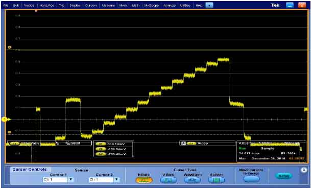 | |
| Fig. 2: | Waveform graph without the function of DCC |
When the amount of light is 3.5 files. the brightest and second gray bright band can be distinguished clearly. The dynamic range calculated is beyond 600% and even reaches 1200%.
It is similar to carry out the dynamic range by calculating the change of aperture value and the ND less-ray stalls. It is a more streamline method to use ND less-ray files in practice.
To avoid the white cutting action effect, it is practical to set a measurement standard of 650 mV.
In the actual measurement, while the amount of light upgrades 3.5 files, the human eyes can still distinguish the boundary line of the brightest times and brighter two gray bright bands in the HD monitor. As it is shown in Fig. 4, the two waveforms of bright band have white cutting phenomenon by the VM 6000 amplitude Article.
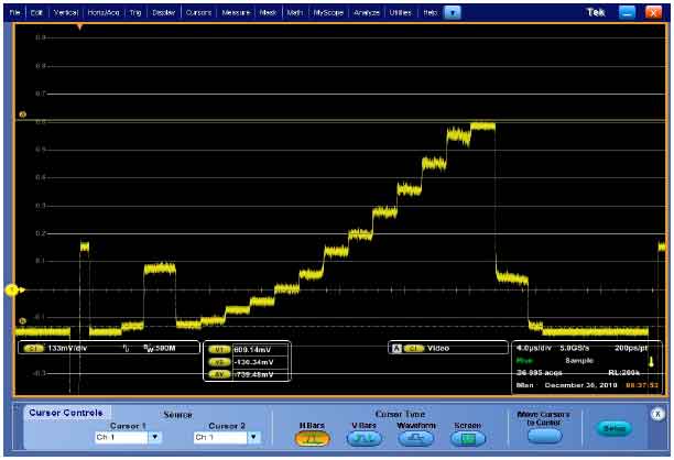 | |
| Fig. 3: | Waveform graph in DCC function |
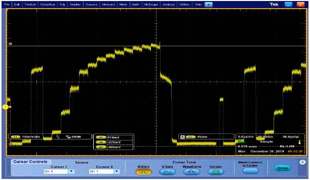 | |
| Fig. 4: | Grayscale waveform diagram when the amount of light of A camera increases of 3.5 files |
CONCLUSION
In resolving power measurement, it is suggested that the precision HD monitor with higher resolution should be selected, or 2K, 4K digital cinema equipment is used to monitor; Different input signal formats directly affect the final measurement results. It should be a unified measurement signal formats, usually using the SDI signal; The aperture should be provided in the optimal lens aperture segment (typically between F5.6-F8) in order to achieve the best measurement result; When the light source brightness is too bright, adding ND less-rays method can make the lens expose normally in optimal aperture segment; Whether gamma and detail level switches are open or not have a great impact on the measurement results. The two should be shut down in measurement; accurate focusing is needed to measure the resolving power. In focus process, the camera focus assist function can be used to achieve precise focus.
In vertical smear measurement. When light reduces by 1/1000, white level goes to 700 mV; The condition has a high demand for the brightness of the white windows. If the brightness of light boxes is not enough, less light requirements can be lowered. The method of changing ND less-rays and electronic shutter will make the light attenuation 1/128 times; The method to speed up the electronic shutter and increase ND less-rays can be used to change the amount of light into lens if there is not 1/1000 Less-rays; Specific measurement line should be set to stipulate in measurement. Amplitude of each line distancing the white window up and down less than 10 lines has a significant change in measurement. The amplitude is very small and changes little over 10 lines; The amplitude values of the corresponding line are basically the same. So it is not necessary to set specific measurement requirement on the top edge or lower edge of the white window.
The aperture is always in the closed state in measurement. So the original method which requires aperture setting and 100% screen luminance signal amplitude is not necessary. (This step verifies the influence of the base gain 0 dB on output amplitude. Same outputs of different apertures indicate different OdB gains); The unweight S/N of 0 dB can be taken as the measuring parameter value and the unweight S/N of +6 dB and +12 dB reference. A low pass filter of 30 MHZ can be used in measuring the HD camera; It is not necessary to raise 5% of the black level elevate of cameras with a digital noise reduction circuit in measurement. However, the black level of those without digital noise reduction circuit should be increased by 5%; Different manufactures set the black level differently. It is suggested that the similar level should be selected in measurement. Aperture stalls alone is not accurate enough to calculate the dynamic range. The amount of light can be increased by changing ND less-rays stalls. Dynamic range is derived by calculating the changed ND less-rays stalls; In measurement, the amplitude of 650 mV can be taken as the standard to avoid white cutting impact on the measurement data; A video measuring instrument is used to help dynamic range measurement. It is the standard to distinguish between the two bright bands when the magnitude between the two gray bright is 20 mV.
REFERENCES
- Hamamoto, Y., K.I. Koyama, S. Okada, H. Murata, M. Nishikawa and N. Itii, 2008. Compact full hd digital movie camera with H.264 codec in single-chip. Proceedings of the IEEE International Symposium on Consumer Electronics, April 14-16, 2008, Vilamoura, pp: 1-3.
CrossRef