
Yuan Jiao
Faculty of Information Science and Engineering, Ningbo University, Ningbo, Zhejiang, China
Li Hong
Faculty of Information Science and Engineering, Ningbo University, Ningbo, Zhejiang, China
Information Technology Journal
Year: 2013 | Volume: 12 | Issue: 10 | Page No.: 1923-1931


ABSTRACT
Virtual Instrumentation (VI) has been widely adopted in test and measurement areas. It has gradually increased applications through continuous LabVIEW innovation and hundreds of measurement hardware devices. Making use of virtual instrumentation technology, a Virtual Integrated Test System (VITS), composed of Oscilloscope, Signal Generator and Transistor Curve Tracer, is presented in this paper. The VITS combines virtual instrument software platform LabVIEW and related hardware based on C8051F320 integrated a complete Full/Low Speed USB function for USB peripheral implementations. This system realizes many functions, including parameters measuring, data acquisition, data storage, data processing according to users’ setting. Experimental results show that this system has such character as low cost, modularization, strong extensibility, very practicality and reliability. Thus, the design has a wide prospect for application.
PDF Abstract XML References Citation
Received: March 19, 2013;
Accepted: May 18, 2013;
Published: July 08, 2013
How to cite this article
Yuan Jiao and Li Hong, 2013. Design of Virtual Integrated Test System Based on USB. Information Technology Journal, 12: 1923-1931.
DOI: 10.3923/itj.2013.1923.1931
URL: https://scialert.net/abstract/?doi=itj.2013.1923.1931
DOI: 10.3923/itj.2013.1923.1931
URL: https://scialert.net/abstract/?doi=itj.2013.1923.1931
INTRODUCTION
With the rapid development of electronics technology and computer technology, the test instruments based on computer gradually attach the attention. Then, the virtual instrumentation, which is a brand-new instrumental concept, has been put forward to the field of automation and electronic measurement (Nan et al., 2005). Virtual Instruments are combination of the traditional instruments and the computers. In the universities, the virtual instruments have the most brilliant prospect in the domain of instruments (Yao et al., 1998). The development of a low-lost multifunctional virtual electronic measuring instrument has a very important significance for improving the students’ practical ability and innovative ability. This paper presents a virtual integrated test system based on Soc C8051F320 integrated USB function and LabVIEW. Three functions are realized in this system, including Oscilloscope, Signal Generator and Transistor Curve Tracer. General construction and working principle of this virtual testing instrument are firstly discussed in this study. Then, the following content respectively introduces the theory and design scheme of each software and hardware module which constitutes the whole virtual testing instrument. Finally, combining with the hardware and software of system, the various functions of the system are tested in this paper. Experimental results show that this system has such character as low cost, modularization, strong extensibility, very practicality and reliability.
FRAMEWORK OF SYSTEM
The overall structure diagram of the system, shown in Fig. 1, can be divided into two parts: hardware and software. Hardware, which is the physical basis of the whole system, provides the platform for software operating. The hardware system consists of Oscilloscope module, Signal Generator module and Transistor Characteristic Instrument module, power and USB control module.
The software system mainly includes the firmware program, the driver program and the user application based on LabVIEW. An appropriate user interface is essential for the users to define how and when the application acquires data from the device, how it processes and stores the data, and how the results are presented.
DESIGN OF HARDWARE
The hardware system, shown in Fig. 2, mainly consists of C8051e circF320 coruit, DDS module, transistor curve tracer circuit, and data acquisition module.
C8051F320 core circuit: The micro-controller used in the system is C8051F320, which is an integrated mixed-signal chip produced by Silicon Laboratories. C8051F320 is fully compatible with the MCS-51’s kernel and instruction set. The maximum speed of the micro-controller is up to 25MIPS. The kernel integrated four general purpose l6-bit counter/timers, 16-bit programmable counter arrays with five capture/compare module.
 | |
| Fig. 1: | Overall structure diagram of the system |
 | |
| Fig. 2: | Structure diagram of the hardware for the system |
The memory integrates the 16K bytes in-system programmable FLASH and 2304 bytes internal RAM. And the peripheral integrates ADC, DAC, UART interface, SPI interface and a temperature sensor.
C8051F320 devices include a complete Full/Low Speed USB function for USB peripheral implementations. The USB Function controller consists of a Serial Interface Engine (SIE), USB Transceiver, 1K FIFO block, and clock recovery mechanism for crystal-less operation. No external components are required (Silicon Labs, 2007a). C8051F320 circuit is shown in Fig. 3.
 | |
| Fig. 3: | C8051F320 circuit |
 | |
| Fig. 4: | DDS circuit: Output1: Analog output of sine wave, Output2: Output of square wave |
 | |
| Fig. 5: | Testing principle: Uc: the input voltage of collector, Ib: the input current of base, Uce: the voltage of collector and emitter, ADC1 and ADC2: The input of the ADC0 subsystem for the C8051F320 |
Data acquisition module: The output of instrument is the analog voltage, which can’t be directly treated by computer. So it must be collected by A/D converter such as AD7821. The AD7821 is a high speed, 8-bit, sampling, analog-to-digital converter that offers a conversion time of 660 ns, 1MHz sample rate and 100 kHz signal bandwidth. It is designed with standard microprocessor control signals and latched, three-state data outputs capable of interfacing to high speed data buses.
DDS signal generator circuit: Direct digital synthesis (DDS) is an important frequency synthesis technology (Dezhi and Caicheng, 2010). The system adopts the DDS chip AD9850. The AD9850 is a highly integrated device that uses advanced DDS technology coupled with an internal high speed, high performance, D/A converter and comparator, to form a complete digitally programmable frequency synthesizer and clock generator function. When referenced to an accurate clock source, the AD9850 generates a spectrally pure, frequency/phase-programmable, analog output sine wave. The AD9850 also contains a high speed comparator that can be configured to accept the filtered output of the DAC to generate a low jitter square ware output. DDS circuit is shown in Fig. 4.
Transistor curve tracer circuit: The system can display the output characteristics of transistor by using integrated operational amplifier, D/A converter and A/D converter etc. Output characteristics curve describes the relationship of collector current and voltage drop when base current is a constant as followings (Hua and Tong, 2006):
| (1) |
The testing principle is shown in Fig. 5. Waveform generator (step wave and sawtooth wave) is composed of TLC7528. The TLC7528 is dual, 8-bit, digital-to-analog converters designed with separate on-chip data latches and feature exceptionally close DAC-to-DAC matching. Data are transferred to either of the two DAC data latches through a common, 8-bit, input port.
 | |
| Fig. 6: | TLC7528 circuit: OUTA: The output of step wave, OUTB: The output of sawtooth wave |
 | |
| Fig. 7: | Voltage-current converter circuit: Ui: the input voltage, Ib: the output current |
Control input DACA/DACB determines which DAC is to be loaded. These devices operate from a 5V to 15V power supply and dissipate less than 15 mW. The TLC7528 is a good choice for many microprocessor-controlled gain-setting and signal-control applications. The TLC7528 circuit is shown in Fig. 6. Because the TLC7528 is operated in voltage mode, which produces a voltage output rather than a current output, voltage-current converter circuit is essential. The voltage-current converter circuit is shown in Fig. 7.
R12 is the base resistance and Ib is output current. According to the circuit, we can get the following equations:
| (2) |
Making R8 = R9 = R10 = R11 = R, we have equations:
| (3) |
| (4) |
| (5) |
Finally, put Eq. 3 and 4 into 5 we have an equation:
| (6) |
It is a simple circuit but has a high-precision voltage-current converter.
DESIGN OF SOFTWARE
The software system mainly includes the firmware program, the driver program and the user application based on LabVIEW.
Firmware program: Firmware program involves the configuration of the firmware and the design of USB communication program to realize data transmission (Xue and Zhao, 2009). The Silicon Laboratories USBXpress Development Kit provides a complete device software solution for interfacing Silicon Laboratories C8051F320 device to the USB. No USB protocol or host device driver expertise is required. Instead, a simple, high-level Application Program Interface (API) for both the host software and device firmware is used to provide complete USB connectivity. The USBXpress firmware library implements a set of device interface functions that provide an API on the C8051F320 microcontrollers (Liu and Dai, 2009).
 | |
| Fig. 8: | Firmware program |
These functions provide a simplified I/O interface to the MCU's USB controller, thus eliminating the need to understand and manage USB protocol details. Figure 8 shows the firmware program.
In general, the user initiates communication with the target USB device by making a call to SI_GetNumDevices. This call will return the number of target devices. This number is then used as a range when calling SI_GetProductString to build a list of device serial numbers or product description strings. To access a device, it must first be opened by a call to SI_Open using an index determined from the call to SI_GetNumDevices. The SI_Open function will return a handle to the device that is used in all subsequent accesses. Data I/O is performed using the SI_Write and SI_Read functions. When I/O operations are complete, the device is closed by a call to SI_Close (Silicon Labs, 2007b).
User application based on LabVIEW: LabVIEW is a proven integrated development environment for interfacing with measurement and control hardware, analyzing data, publishing results, and distributing systems using a graphical programming approach. Its greatest feature is the graphical programming language, easy to grasp and understanding, realistic user interface. LabVIEW programs are called virtual instruments, or VIs. The components of a VI are as follow: Front panel which serves as the user interface, block diagram which contains the graphical source code that defines the functionality of the VI, icon and connector pane which identifies the VI so that you can use the VI in another VI (Yang, 2005). The Silicon Laboratories USBXpress Development Kit provides a complete host software solution for interfacing Silicon Laboratories C8051F320 device to the USB. The host API is provided in the form of a Window Dynamic Link Library (DLL). The host interface DLL communicates with the USB device via the provided device driver and the operating system's USB stack. LabVIEW programmers can access Window Dynamic Link Library (DLL) through the Call Library Function (Xia et al., 2009). The Call Library Function icon is located in the Advanced Subpalette of the Function palette. The main block diagram of Oscilloscope is shown in Fig. 9. The front panel of Oscilloscope is shown in Fig. 10.
EXPERIMENTAL RESULTS
Three functions are realized in the system, we have tested respectively for the virtual Oscilloscope, the virtual Signal Generator and the virtual Transistor Curve Tracer.
Virtual signal generator: The mission requirements of the virtual signal generator are as follows: The sine wave and square wave can be produced, and the frequency range of the waveform is from 1Hz to 1MHz, and the amplitude range of sine wave is from 0.1V to 2.5V.
For proving the correctness of the module, an experimental sin signal, whose frequency is 100Hz and amplitude is 1V, is generated by virtual signal generator. The result is shown in Fig. 11. According to the result, displayed by TDS-3032B oscilloscope, it shows that the virtual signal generator is reliable.
Virtual oscilloscope: The design requirements of the virtual oscilloscope are as follows: The sample rate is optional, and the range is from 500Hz to 1MHz. Moreover, it offers 100kHz signal bandwidth. The maximum input voltage is 20V.
 | |
| Fig. 9: | Block diagram of oscilloscope in the LabVIEW |
 | |
| Fig. 10: | Front panel of oscilloscope in the LabVIEW |
For proving the reliability of the module, standard sinusoidal signals, whose amplitudes are 2.5V, are generated by YB1602 function signal generator. And the frequencies of signals respectively are 100Hz, 10kHz. The results, displayed by the virtual oscilloscope, are shown in Fig. 12. Furthermore, standard square wave and triangular wave, whose amplitude is 1.5V and frequency is 10kHz, are displayed by virtual oscilloscope as Fig. 13. Comparing with standard signals, the results show the practicality and reliability of the system.
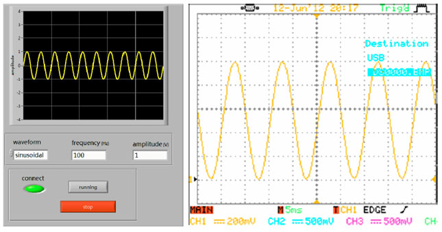 | |
| Fig. 11: | Waveform generated by virtual signal generator |
 | |
| Fig. 12(a-b): | Sinusoidal signals displayed by virtual oscilloscope (a) 100 H2 sinusoidal wave and (b) 10 H2 sinusoidal wave |
 | |
| Fig. 13(a-b): | Standard signals displayed by virtual oscilloscope (a) 10 kH2 sinusoidal wave and (b) 10 kH2 triarq law wave |
 | |
| Fig. 14: | Synchronization of waveform |
 | |
| Fig. 15: | Output characteristics curve of transistor 9013 |
| Table 1: | Accuracy testing of DC current gain (hFE) |
 | |
Virtual transistor curve tracer: The test object of the virtual transistor curve tracer is low-power transistors, which are commonly used in laboratory, such as 9013, 8050 and so on.
The previous analysis shows that step wave and sawtooth wave are synchronous. The relationship of waveforms is shown in Fig. 14. The accuracy of DC current gain (hFE) value is an important indicator of measurement of virtual transistor curve. Comparing with calibration value measured by VICTOR 98A digital multimeter, the experimental value measured by virtual transistor curve tracer is very near. The measurement data are shown in Table 1. It can be drawn from the table that the maximum error is 0.5%. Moreover, the output characteristics curve of low-power transistor 9013 is shown in Fig. 15. So it meets the criteria of the original design.
CONCLUSION
This paper presents a multifunctional, low-cost and USB-based virtual integrated design of experimental apparatus. The instrument integrates some commonly used electronic test instruments such as Oscilloscope, waveform generator, Transistor Characteristic Instrument in one, having small size, low cost, etc. The design of Virtual Integrated Measure System based on USB, which makes the most efficient use of the integrated resources of C8051F320. This design can not only realize the function of the traditional measuring instrument, but also can save measurement data to observe and analyze repeatedly. The paper also provides a good solution for the USB interface device for data acquisition and storage. So the design has a very wide prospect for application.
ACKNOWLEDGMENT
This work is supported by the Experiment Technology Research and Development Project of Ningbo University (SYJS-201201), Zhejiang Bud Talent Plan (2012R405029), Postgraduate Key Course Construction Project of Ningbo University (YJ2011KC03).
REFERENCES
- Yao, Y., Y. Bowen and Z. Pan, 1998. Virtual instrument system for teaching lab. Wuhan Univ. J. Natural Sci., 3: 319-322.
CrossRefDirect Link - Dezhi, X. and D. Caicheng, 2010. Study and realization of a signal generator based on the DDS technology. J. Elect. Sci. Technol.
Direct Link - Liu, P.F. and Q.J. Dai, 2009. Design of low-cost ECG monitoring system based on C8051F320. Electron. Design Eng., 10: 46-51.
Direct Link