
Liu Shi
The State Key Laboratory for Manufacturing Systems Engineering, Xian Jiaotong University, Xian, Shaamxi, 710049, The Peoples Republic of China
Journal of Applied Sciences
Year: 2005 | Volume: 5 | Issue: 3 | Page No.: 465-469


ABSTRACT
This study develops a novel balancing method named as Low-Speed Holo-Balancing (LSHB), which can balance the flexible rotor without test run at high speeds. The principle of LSHB is mainly based on the holospectrum technique with following specialties. Firstly, the vibration response of rotor is described by three-dimensional holospectrum using multi-sensor fusion, instead of information from a single sensor. Secondly, the variation rules of the first two modal components are studied through the information in run-up or run-down stages. Then we can deduce the vibration responses at high speed from that at low speed. Finally, the first two modal components can be corrected simultaneously at the speed below the first critical speed. The advantages of LSHB are that the safety of balancing increases because the rotor need not run at high speed or at critical speeds as the traditional modal balancing method do, also the number of test runs and corresponding wastages decrease. The effect of method was validated by the experiments on a flexible rotor test rig.
PDF Abstract XML References Citation
How to cite this article
Liu Shi, 2005. A Modified Balancing Method for Flexible Rotors Based on Multi-sensor Fusion. Journal of Applied Sciences, 5: 465-469.
DOI: 10.3923/jas.2005.465.469
URL: https://scialert.net/abstract/?doi=jas.2005.465.469
DOI: 10.3923/jas.2005.465.469
URL: https://scialert.net/abstract/?doi=jas.2005.465.469
INTRODUCTION
The balancing of flexible rotors is one of the pivotal techniques for high-speed rotating machinery in modern industry. In general, high speed balancing procedure must be applied for flexible rotors after low-speed balancing, because the balance situation of rotor in low speed has been changed in high operating speed. These high speed balancing methods for flexible rotors fall into two categories[1-3]: modal balancing and influence coefficient balancing. The traditional low-speed rigid-rotor balancing is also applied for flexible rotor, but it is only a prelude to later flexible-rotor balancing. This is done to remove the gross unbalances first before attempting to approach the first critical.
The intention of this study is to propose a new low-speed balancing method for high-speed rotating machinery running at the speed between the first and second critical speeds. It is not rigid-rotor balancing, but the extension of flexible-rotor balancing methods. The first two modal components of unbalance can be balanced simultaneously at the speed below the first critical speed. This method is named as Low-Speed Holo-Balancing (LSHB), by which the satisfactory results can be obtained as that at high speed. The rotor needs not run at high speed or critical speeds to achieve satisfactory balance. In this method, the three-dimensional holospectrum is used to describe the vibration response of rotor unbalance. It is constructed from vibration information of rotor system in all bearing sections based on the multiple sensor fusion in data layer. Since the frequency, amplitude and phase information are fully utilized, the three-dimensional holospectrum can increase the balancing accuracy and efficiency. The effect of new method was validated by the experiments on a flexible rotor test rig.
HOLOSPECTRUM TECHNIQUE
Description of unbalance responses: In most traditional balancing methods, only the vibration information in one measuring direction is used. This is based on the assumption of equal rigidity in different circumferential directions of rotor-bearing system. The errors would occur when the rigidity is different. From the viewpoint of information fusion, it is quite desirable to examine the vibration in a bearing section as a whole, not on individual measuring points. The Initial Phase Point (IPP) on holospectrum effectively fuses information from two sensors in one rotor section and can entirely describe the vibration behavior of rotor in the measuring section[4,5]. Suppose that:
 | (1) |
 | |
| Fig. 1: | The initial-phase point (IPP) on the 1x ellipse |
 | |
| Fig. 2: | Configuration of balancing rig x15 |
are the synchronous responses of signals picked up from two mutually perpendicular directions X and Y. Equation (1) can be regarded as the equation of rotor synchronous rotating orbit or 1X ellipse (Fig. 1). We define the IPP as the point on first harmonic frequency ellipse, where the key slot on the rotor locates straightly opposite to the phaser. The initial-phase point (IPP) of holospectrum is defined as
| (2) |
Relationship between initial phase point and trial weights: The experimental rotor rig, which simulates unbalance behavior, is shown in Fig. 2. The numbers 1 to 4 denote the proximity probes measuring the radial vibrations of the rotor in two sections A and B, 5 is the phaser. Both C and D are the two balancing discs. The first critical speed of the rotor is about 2700 rpm and the operating speed of the rotor is about 4600 rpm.
The experiment was held as follows:
| 1. | Adding the trial weights on two discs C and D to simulate the initial force unbalances: TC = TD = 1.0gp0° . Then, run up to 4600 rpm, measured the rotor original vibrations in both X and Y directions and drew 3D-holospectra. |
| 2. | Changing the mounting angles of trial weights from 0 to 360° with equal intervals 45°, measured the vibration and got 8 groups of 3D-holospectra. The phases of IPPs drawn in a plot are shown in Fig. 3a, which shows the linear relationship between the initial phases and the mounting peripheral angle of trial weights. |
 | |
| Fig. 3: | Relationship between Initial Phase Point and trial weights: a) Linear relationship between the initial phases of vibrations and the mounting angles of trail weights; b) Linear relationship between the modulus of IP vectors and the magnitudes of trail weights |
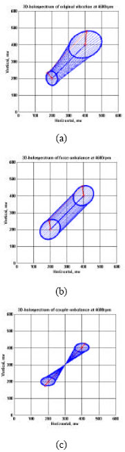 | |
| Fig. 4: | The decomposition of the 3-dimensional holospectra: a) the original unbalance response under the speeds of 4600 rpm; b) the decomposed force components at same speeds; c) the decomposed couple components |
| 3. | Changing the magnitudes of trial weights from 0.2 to 1.6 g with equal interval 0.2 g, measured the vibration and got eight groups of 3D-holospectra. The moduli of IP vectors keep the linear relationship with the trial weights, as shown in Fig. 3b. |
Decomposition of 3D-holospectrum: A 3-dimensional holospectrum is composed of 1X ellipses with IPPs, IP vectors and generating lines connecting corresponding sampling points around all 1x ellipses. Such a 3-dimensional holospectrum can provide us full information of rotor vibration simultaneously in all bearing sections as a whole. Figure 4a shows a 3-dimensional holospectrum, which is composed of 1x ellipses in two bearing sections. The unbalance response expressed as a 3-dimensional holospectrum can be decomposed into the force and couple responses[6]. Parallel generating lines indicate force unbalance (Fig. 4b) and the intersecting lines indicate the couple unbalance (Fig. 4c).
VARIATION RULES OF UNBALANCE RESPONSES
Assuming the influence of higher modal components can be neglected equation and only the first two low modal components of unbalance will be considered, the unbalance response at the operating speed Ω without damping effects can be rewritten[1,2]
| (3) |
where, ω1 is the first critical speed, ω2 is the second critical speed, ω is the speed of low-speed balancing below the first critical speed ω1, Ω is the operating speed between ω1 and ω2, ![]() is force unbalance response,
is force unbalance response, ![]() is coupling unbalance response[6]. As above, get
is coupling unbalance response[6]. As above, get ![]() The phase change of force unbalance component is
The phase change of force unbalance component is
| (4) |
The phase change of coupling unbalance component is
| (5) |
The amplitude change of force unbalance component is
| (6) |
The amplitude change of coupling unbalance component is
| (7) |
When there exists the damping effect, the phase of force unbalance component inverses approximately180° and the phase change of couple unbalance component is approximately equal to 0°, which are consistent with experimental results as shown in Fig. 5.
 | |
| Fig. 5: | Bode diagram of unbalance response in the A plane: a) Force component; b) couple component |
LOW-SPEED HOLO-BALANCING OF A FLEXIBLE ROTOR
As discussed above, it can be seen that when δf, δc, rf and rc are all known, the unbalance response at high operating speed can be deduced from that at low speed below the first critical speed, according to equation (4-7). Thus, the rotor balancing does not have to be operated at high operating speed. Based on it, a new balancing method called as ISHB, is proposed for balancing flexible rotor. In this section, we will discuss the implementation process and validity of the new method in details through a balancing case.
The configuration of experimental rotor rig is shown in Fig. 2. The operating speed of rotor is Ω = 4600 rpm and the balancing speed is ω = 1900 rpm.
The balancing steps are as follows:
| 1. | At one run-down stage, the vibrations caused by the original unbalance are measured at speeds both Ω and ω. From equation (2), get RΩ(sA), RΩ(sB), Rω(sA) and Rω(sB). |
| 2. | The trial weights are added on two balancing discs to simulate the force unbalance, T1C = T1D = 1.0gp270°. Rotor vibrations including Rω1 (sA) and Rω1 (sB) are measured at speed ω and then the test weights T1C and T1c are taken off. |
| 3. | The trial weights are added on two balancing discs to simulate the couple unbalance in the second run: T2C = 1.0 gp45°, T2D = 1.0 gp225°. Rotor vibration in Rω2 (sA) and Rω2 (sB) are measured at speed ω and then the test weights T2C and T2C are taken off. |
| 4. | Calculating δf and rf: through the decomposition of 3D-holospectrum, RΩ(s), Rω(s) can be decomposed as equation (3). Inserting the decomposed results into equation (3) and (6) gives δf = -145.7° and rf = 1.47. |
| 5. | Calculating δc and rc: δc = 9.6° and rc = 5.0. |
| 6. | Calculating the vibration response of the unit force unbalance weights at the speed ω |
| (8) |
| 7. | Calculating the vibration response of the unit couple unbalance weights at the speed ω |
| (9) |
| 8. | The correcting weights on two balancing discs for force unbalance can be calculated |
 | (10) |
Similar to equations (5.4), the correcting weights for couple unbalance can be calculated
 | (11) |
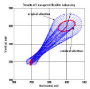 | |
| Fig. 6: | Results of Low-speed holo-balancing |
| Table 1: | Effects of Low-speed holo-balancing |
 | |
The total correcting weights can be calculated, Pc = 1.19gp104.0° and PD = 0.57gp280.9. Adding the correcting weights PC and PD, then running up to 4600 rpm and measuring the rotor residual vibrations R’(sA) and R’(sB). The measuring results in detail are listed in Table 1. The vibration responses expressed by the 3D-holospectra, before and after correction by the Low-speed holo-balancing method, are shown in Fig. 6. The thin lines represent the original vibrations and the bold lines represent the residual vibrations. Using this Low-speed holo-balancing technique, vibration levels of an experimental rotor rig were successfully reduced to as much as 50% of their original levels. It is evidential that the correction weights are reasonable and the new balancing method is effective.
CONCLUSION
This study presents a new balancing method, named low-speed holo-balancing. It is an extension of flexible rotor balancing method, but avoids test runs at high operating speed or critical speeds in the balancing process. The key features of new method are that the vibration responses of rotor are described by three-dimensional holospectrum and the decomposition of holospectrum are employed to investigate the variation rules of first two modal components at the run-up or run-down stages. The first two modal components can be canceled simultaneously at the speed below the first critical speed of flexible rotors. Experimental results showed that this new method can reduce the rotor vibration due to unbalance effectively, safely and conveniently.
ACKNOWLEDGMENT
This study was supported by the National Natural Science Foundation of China under grant number 59335033.
REFERENCES
- Xu, B.G. and L.S. Qu, 2001. A new practical modal method for rotor balancing. Proc. Inst. Mech. Eng., 215: 179-189.
Direct Link - Tan, S.G. and X.X. Wang, 1993. A theoretical introduction to low speed balancing of flexible rotors: Unification and development of the modal balancing and influence coefficient techniques. J. Sound Vibrat., 168: 385-394.
Direct Link