
A. Hamel
Department of Physics, University 08 May 1945, Guelma 24000, Algeria
A. Chibani
Department of Physics, University Badji Mokhtar, Annaba, Algerie
Journal of Applied Sciences
Year: 2010 | Volume: 10 | Issue: 3 | Page No.: 231-234


ABSTRACT
There is a significant gap between the textured surface with three successive reflections of new solar cell prototype with an anti-reflective layer and without an anti-reflective layer. This study concerns in particular the photovoltaic parameters such as the spectral response, the absorption coefficient and the generation rate. We have found that we are getting nearer to the ideal values in case we want to take advantage of ray incidence three times with an anti-reflective layer, then we will get good results. We have investigated with an anti-reflective layer and hence, making the penetrating rays rate to reach 90%, leading to the improvement of the spectral response, the absorption coefficient, the generation rate.
PDF Abstract XML References Citation
How to cite this article
A. Hamel and A. Chibani, 2010. Characterization of Texture Surface for Solar Cells. Journal of Applied Sciences, 10: 231-234.
DOI: 10.3923/jas.2010.231.234
URL: https://scialert.net/abstract/?doi=jas.2010.231.234
DOI: 10.3923/jas.2010.231.234
URL: https://scialert.net/abstract/?doi=jas.2010.231.234
INTRODUCTION
Photovoltaic materials (Grasso et al., 2005; Moller et al., 2005; Shah et al., 2003; Metzdorf et al., 2000; Lawrence et al., 2000; Mashanovich et al., 2008; Usuda et al., 2007) are distinguished by an index of refraction greater then 3 and a high reflection coefficient in the visible spectrum.
The reflection can be more reduced by covering the cell surface with an anti-reflective layer in order to bring the percentage of the reflected rays to a reasonable value. In effect a normal plane of silicon can reflect up 35% of the received rays (Goetzberger et al., 2003). This rate can be reduced to 10% if the plane is covered with an anti-reflective layer (Caneau et al., 1993) and hence, making the penetrating rays rate to reach 90%. With the model of three successive reflection (Hamel et al., 2009) can be minimized to less than 10%, leading to the improvement of the spectral response, the absorption coefficient and the generation rate.
TEXTURED SURFACE WITH THREE SUCCESSIVE REFLECTIONS
The model suggested in this study allows the material to have three successive absorptions of the incident rayon, by varying the incident angle i, the aperture between the pyramids f and their height h (Height varying between 5 and 10 μm).
This model is based on reflection and refraction laws of incident rays on the surfaces of two neighbouring pyramids. By considering N the number of rays that are incident on the surface of the pyramid I and r the reflection coefficient, the proportion of the absorbed rays by the material is given by N(1-r) whereas, that of the reflected rays is Nr. These tatters fall on the surface of the pyramid 2 where they are absorbed with Nr(1-r) proportion, while Nr2 proportion is reflected. A change of the aperture between the summits the neighbouring pyramids will allow the Nr2 rays to fall a second time on pyramid I (Fig. 1).
This mechanism will permit to recuperate an third proportion of the incident rays Nr2 (1-r), that will participate to the improvement of the photovoltaic properties such as the spectral response, the absorption coefficient and generation rate. The total amount of the absorbed rays in the sum of the three successive incidences and is given by N (1- r3).
Let φ to be the angle between the incident ray Nr2 and the face of pyramid 1 and α the angle between the two neighbouring pyramids:
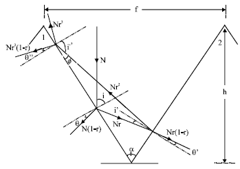 | |
| Fig. 1: | Textured surface with three successive reflections |
| Table 1: | Incidence and refraction angles |
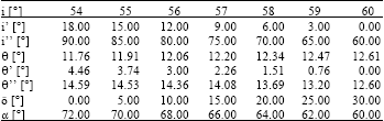 | |
| i: 1er incidence angle, i’: 2ème incidence angle, i’=: 3ème incidence angle, θ: 1er refraction angle, θè’: 2ème refraction angle, θ’=: 3ème refraction angle, φ: angle between the incident ray Nr2 and the face of pyramid I, α: angle between the two neighbouring pyramids | |
| Table 2: | Distance between the summits of two neighbouring pyramids |
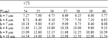 | |
| i: incident angle, f : aperture between the summits of the two neighbouring pyramids | |
| (1) |
The sum of a triangle angles is π, Thus:
| (2) |
And as φ>0 then:
| (3) |
If i represents the angle of the first projection on the surface of pyramids 1 and i’ the angle the second projection on the surface of the second pyramid then:
| (4) |
In the case of crystalline silicon and for wave length λ = 590 nm; the application of Snell‘s law between the surfaces of the pyramids 1 and 2, permits to obtain the refraction angles θ, θ’, θ’=. The angles correspond respectively to the incidences angles i, i’ and i’= (Table 1).
The aperture f between the summits of the two neighbouring pyramids is given by the relation:
| (5) |
The calculated values of f for different heights h and different incidence angles i are assembled in Table 2.
ANTI-REFLECTIVE LAYER
One way to mix angles is bay photon re-absorption and re-emission, but this requires extremely good material quality and low parasitic absorption.
 | |
| Fig. 2: | Typical photon trajectories. (a) In the planer structure, photons’ trajectories are randomized by self-absorption/re-emissions events represented by dots (photons recycling) and (b) in the textured surface, angular randomization is achieved by strong surface |
Photon recycling implemented with high quality material (Fig. 2a).
However, it was also demonstrated that this high external efficiency is very susceptible to parasitic loss mechanisms (free-carrier absorption in doped layers, for example) or slight degradation in the internal quantum efficiency. Angular randomization by photon recycling is not practical since, it is vulnerable to the slightest deterioration of material or mirror quality. A more practical approach and the one which we adopt here, is angular randomization by scattering of the photons from textured semiconductor surfaces. Thus, the textured surface geometry, schematically shown in Fig. 2b, can boost the external efficiency to 50% or more.
SPECTRAL RESPONSE, ABSORPTION COEFFICIENT AND GENERATION RATE
The spectral response is an essential parameter in the characterization of solar cells for a silicon normal plane this parameter in given by the relation:
| (6) |
where, N(1-r) represents the proposition of absorbed rays.
For a textured plane the Eq. 6 becomes:
| (7) |
where, N(1-r2) represents the absorbed rays. By applying the model that uses three successive incidences, the Eq. 7 becomes:
| (8) |
where, N(1-r3) represents the absorbed rays. If we write x = Pph/qN we get:
| (9) |
The absorption coefficient varies linearly with the incident rays; this coefficient is given by the equation:
| (10) |
where, d is the cell thickness.
Thus:
| (11) |
and
| (12) |
The generation rate is given by the equation:
| (13) |
If we cover the surface of the cell with an anti-reflective layer we will get good results especially for the treated plan surface where reflection coefficient r is near zero and consequently the spectral response, the absorption coefficient and the generation rate increases almost to the ideal values, which helps improve In Fig. 3 sums up what has been mentioned above for the various wavelengths located in the visible spectrum.
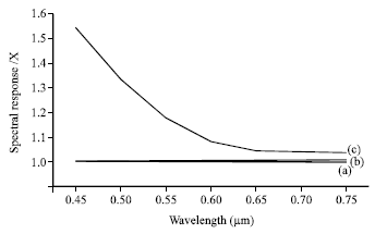 | |
| Fig. 3: | Spectral response vs. wavelength. (a) ideal case, (b) with an anti-reflective layer (d = 0, 12 μm) and (c) without an anti-reflective layer |
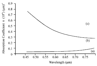 | |
| Fig. 4: | Absorption Coefficient Vs. wavelength. (a) ideal case, (b) with an anti-reflective layer (d = 0, 12 μm) (c) without an anti-reflective layer |
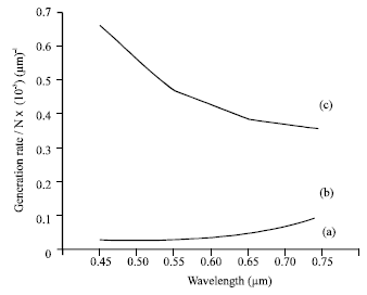 | |
| Fig. 5: | Generation rate Vs. wavelength. (a) ideal case, (b) with an anti-reflective layer (d = 0, 12 μm) and (c) without an anti-reflective layer |
Figure 4 and 5, show the variation of the absorption coefficient and the generation rate against the various wavelengths located in the visible spectrum.
These results show that these two parameters approach also the theoretical ideal case.
CONCLUSION
This study is based on the use of the anti-reflective layer on the surface of textured planes of solar cells, in order to improve the photovoltaic efficiency. For achieving this goal we developed a model that can recuperate a second reflection instead of one currently, by varying the incidence angle and the aperture between the neighbouring pyramids. This model permits the solar incident rays to have three successive absorptions by the material. The calculations of incidence angles on the pyramids surfaces and the aperture f between the neighbouring pyramids were carried out for different pyramid heights. The application of the suggested model shows a significant improvement of the photovoltaic parameters such as the spectral response, the absorption coefficient and the generation rate.
The representative curves of these parameters in the case of this model approach those representing the ideal case and if we cover the surface of the cell with an anti-reflective layer we will get good results. In conclusion we can say that this model can contribute to a significant improvement of the photovoltaic efficiency and can be applied to other photovoltaic material.
REFERENCES
- Grasso, C., A. Goossens and M. Burgelman, 2005. Electron transport in CuInS2-based nanostructured solar cells. Thin Solid Films, 480-481: 87-91.
CrossRefDirect Link - Moller, H.J., C. Funke, M. Rinio and S. Scholz, 2005. Multicrystalline silicon for solar cells. Thin Solid Films, 487: 179-187.
CrossRefDirect Link - Shah, A.V., J. Meier, E. Vallat-Sauvain, N. Wyrsch, U. Kroll, C. Droz and U. Graf, 2003. Material and solar cell research in microcrystalline silicon. Solar Energy Mater. Solar Cells, 78: 469-491.
Direct Link - Metzdorf, J., S. Winter and T. Wittchen, 2000. Radiometery in photovoltaics: Calibration of reference solar cells and evaluation of reference values. Metrologia, 37: 573-578.
CrossRef - Mashanovich, G.Z., M. Milosevic, P. Matavulj, S. Stankovic and B. Timotijevic et al., 2008. Silicon photonic wave guides for different wavelength regions. Semicond. Sci. Technol., 23: 9-9.
CrossRef - Usuda, K., T. Irisawa, T. Numata, N. Hirashita and S. Takagi, 2007. Characterization of in-plane strain relaxation in strained layers using a newly developed plane nano-beam electron diffraction (plane-NBD) method. Semicond. Sci. Technol., 22: S227-S230.
CrossRef - Hamel, A., B. Hadjoudja, B. Chouial and A. Chibani, 2009. Modelisation of the incident solar rays on the textured surface of the solar cells. Asian J. Mater. Sci., 1: 8-13.
CrossRefDirect Link - Goetzberger, A., C. Hebling and H.W. Schock, 2003. Photovoltaic materials, history, status and outlook. Mater. Sci. Eng., 40: 1-46.
CrossRefDirect Link