
Deng Xin
Huazhong University of Science and Technology, China
Zhao Jin
Huazhong University of Science and Technology, China
Geng Tao
Huazhong University of Science and Technology, China
Liu Yang
Huazhong University of Science and Technology, China
Information Technology Journal
Year: 2009 | Volume: 8 | Issue: 8 | Page No.: 1150-1159


ABSTRACT
This study proposes the full order observer feedback gain and adaptive speed PI design methods in speed sensorless induction motor drive. The characteristic of speed estimation plant function, which has impact on adaptive speed estimation PI design, is influenced by the feedback gain design. It is found that poor damping exists when feedback gain is zero and a simple, parameter independent feedback gain design method is introduced. Estimated speed steady state accuracy, noise sensitivity and the relation between speed estimation loop and speed control loop are the affecting factors in adaptive speed estimation PI design. The method of adaptive speed estimation PI design is proposed according to the speed control loop. Steady state and dynamic performance of the sensorless drive using simulation are demonstrated.
PDF Abstract XML References Citation
How to cite this article
Deng Xin, Zhao Jin, Geng Tao and Liu Yang, 2009. Design of Full Order Observer in Speed Sensorless Induction Motor Drive. Information Technology Journal, 8: 1150-1159.
DOI: 10.3923/itj.2009.1150.1159
URL: https://scialert.net/abstract/?doi=itj.2009.1150.1159
DOI: 10.3923/itj.2009.1150.1159
URL: https://scialert.net/abstract/?doi=itj.2009.1150.1159
INTRODUCTION
In recent years, much endeavor has been made to improve the performance of speed sensorless control system, especially in the low speed range. Various estimation schemes (Schauder, 1992; Yang and Chin, 1993; Cirrincione et al., 2006, 2007; Holtz and Quan, 2003; Kubota et al., 1993; Yan et al., 2000; Kim et al., 1992; Ohtani et al., 1992) have appeared, among which the adaptive seems to be the most promising one. The rotor flux MRAS structure due to Schauder (1992) is easy to understand and most widely referenced in literature. The MRAS structure based on torque current due to Ohtani et al. (1992) is not so well known but selected because of its claimed better performance. They are both a representative method that requires pure integration and is faced with high sensitivity to stator resistance in reference voltage mode. And what’s more, the speed is estimated in close loop, while motor flux is in nature open-loop observed in current model.
Full order observer applied to estimating speed and flux in speed sensorless control system is based on the electromagnetic dynamic equation of motor. The motor itself and full-order observer as the reference and adjustable model, respectively, the observer estimates stator current and adjust the estimated speed until the error between estimated and measured stator current towards zero. Hinkkanen makes research in full order observer digital implementation and considers the discrete error effect (Hinkkanen and Luomi, 2001). It is shown that the popular Euler discretization method will make the error larger with motor speed increasing and finally enter instability region. At the same time, the case in different observer coordinates will be different (Hinkkanen and Luomi, 1998). Corresponding strategies are given by Hinkkanen and Luomi (2001), Hinkkanen and Luomi (1998) and Maes and Melkebeek (2000). In order to let the corresponding estimated state variables converge much faster, Kubota et al. (1993) proposed allocating the observer poles to be k times those of motor, while Maes and Melkebeek (2000) proposed shifting to left. Both of them were just from the point of observer state matrix stability and convergence, lacking in speed estimation loop influence consideration. In fact, there exists an unstable region in full-order observer based speed sensorless system for its uncompleted speed adaptive law and many studies deal with it (Suwankawin and Sangwongwanich, 2002, 2006; Harnefors and Hinkkanen, 2008; Hofmann and Sanders, 1998; Hinkkanen and Luomi, 2004; Kubota et al., 2002). Suwankawin and Sangwongwanich (2006) focuses on the adaptive PI design with ramp response characteristic of speed estimator as guidelines. It is revealed that the integral adaptation gain determines the tracking error with sensitivity to measurement noises depending on proportional gain. Excellent dynamic and steady performance even in low speed range is demonstrated in the study.
In this study, detailed analysis is made on the design of full order observer in speed sensorless induction motor drive. The characteristic of speed estimation plant function is examined and it is found that poor damping ratio exists when the feedback gain is zero. Meanwhile it is discovered that it does not only speed up the convergence rate of state variables, but also improves the damping ratio to left shift the corresponding characteristic value of plant function. Therefore, a simple, parameter independent feedback design is introduced. Steady state accuracy and noise sensitivity of speed estimation are analyzed. In addition, the harmony between estimation loop and control loop has to be maintained to obtain excellent tracking performance. All these together determine the PI design. The validity of the proposed design is proven through digital simulation.
INDUCTION MOTOR AND ADAPTIVE FULL ORDER OBSERVER MODEL
The symbols used in the study are as follows:
| Rs | : | Stator resistance |
| RR | : | Rotor resistance |
| LM | : | Magnetizing inductance |
| LÓ | : | Total leakage inductance |
| σr | : | Rotor time constant |
| ωe | : | Motor synchronous angular frequency |
| ωm | : | Motor rotor electrical angular frequency |
| ωb | : | Motor base speed |
| ωk | : | Reference coordinate rotating angular frequency |
| ωsl | : | Motor slip angular frequency |
| us | : | Stator voltage space vector |
| is | : | Stator current space vector |
| ψs | : | Stator flux space vector |
| ψR | : | Rotor flux space vector |
| eØ | : | Rotor flux error |
| e | : | State variable error |
| ei | : | Stator current error |
| eù | : | Rotor speed error |
| eq | : | q-axis current error |
| Ts | : | Sampling period |
The inverse-⌈ induction model is considered (Fig. 1). Space vectors without superscript are expressed in arbitrary coordinate, whereas superscripts s and r indicate stator and synchronous rotating coordinates, respectively.
 | |
| Fig. 1: | Equivalent circuit for the inverse-⌈ model |
A hat is used to denote an estimated quantity. A 5.5 kW motor with 2 pole pairs is used here.
In arbitrary reference coordinate, induction motor can be expressed with stator and rotor flux as state variables.
 | (1a) |
 | (1b) |
Where:  |
Full order observer can be constructed as Eq. 2, based on induction motor equation Eq. 1 when motor parameter errors are not considered.
| (2a) |
| (2b) |
Where:  |
The rotor speed is estimated using the speed adaptation law:
| (3) |
| (4) |
where, ε is the adaptive signal; kp and ki are proportional and integral coefficients, respectively; superscript * indicates complex conjugate; Im{} means the imaginary part of complex.
The state variable and stator current error can be obtained by subtracting Eq. 2 from Eq. 1:
 | (5a) |
| (5b) |
Where:
 |
The transfer function from speed error eù to the stator current error ei is:
 | (6) |
Where:
 |
 | |
| Fig. 2: | Close loop speed estimation |
 |
Combining and orienting equations Eq. 3, 4 and 6 in synchronous rotating frame, the speed PI controller function and plant function can be obtained, respectively with ωk set ωe.
| (7) |
| (8) |
Where:
Using Eq. 7 and 8, close loop speed estimation is shown in Fig. 2. The open loop transfer function is derived.
| (9) |
CHARACTERISTICS OF PLANT FUNCTION
The observer feedback gain is designed zero first, to allow the estimated state variables having the same convergence rate with motor itself. Equation 8 demonstrates that the plant function has one real and a couple of conjugate complex zeros and two couples of conjugate complex poles. Their locations in s plain have relations with ωm and ωsl.
Figure 3a and b show the zeros and poles of plant function with zero slip frequency in base speed range and it can be seen that the damping ratios are poor with speed increasing. Figure 4a and b is the corresponding bode diagram, where it can be found that the magnitude and phase shift will oscillate near the operating frequency. Moreover, the largest phase shift of plant function almost occurs at the operating frequency.
 | |
| Fig. 3: | Zeros and poles of plant function with zero slip frequency, (a) zeros and (b) poles |
 | |
| Fig. 4: | (a, b) Bode diagrams of plant function with zero slip frequency |
The largest phase shift will get more and more negative and pass -90° with speed increasing. And it is almost the same for the case with other slip frequency and what’s more, the largest phase shift will be larger with slip frequency increasing in certain speed.
The largest phase shift of plant function, near or passing -90°, determines that the corner frequency of PI controller has to be designed carefully so that the open loop transfer function Eq. 9 has enough stability margin. Equation 10 shows the stability phase relation and Eq. 11 the phase calculation of PI controller.
| (10) |
| (11) |
where, ∠Gω, ∠Gq denote the phase shift of plant function and PI controller, respectively. Υ is the phase stability margin, ωc= ki/kp, ωc is the corner frequency of PI controller.
From Eq. 11, the phase shift of PI controller decreases with frequency, towards zero in infinity. Based on the largest phase shift in Fig. 4, it is supposed that the largest of be -110° and phase margin Υ be 10°, the corner frequency of controller is obtained:
| (12) |
It is demonstrated in Eq. 12 that corner frequency has upper limit related with operating frequency to maintain stability in the whole speed range. Through simulation, it is found that is enough to ensure stability in whole range.
FEEDBACK GAIN DESIGN STRATEGY
The poor damping of the numerator and denominator makes the plant function oscillate near operating frequency and directly constrains the corner frequency of PI controller. Maes proposed the method to left shift the zeros and poles of plant function to obtain reasonable damping ratio, however, it involves much calculation and high parameter sensitivity.
Equation 13 shows a similar feedback design method to left shift the roots. The real part of roots left shift, but in fact, the corresponding imaginary part takes tiny change and the effect is little and negligible. The method indeed does not depend on parameters and is very simple.
 | |
| Fig. 5: | (a, b) Bode diagrams of plant function with zero slip frequency using Eq. 13 |
| (13) |
Where:
 |
Rn can be determined according to motor.
Figure 5a and b show the bode diagram of plant function using Eq. 13. The oscillation near the operating frequency gets much smaller. And so is the largest phase shift near the operating frequency, which can help increase the corner frequency of PI controller to speed up the dynamic performance of estimation loop.
SPEED ESTIMATION PI DESIGN STRATEGY
A measure of the speed of response of adaptive speed loop is the adaptive natural frequency ωad and it is found that low sensitivity to Rs is influenced by it. Besides, when designing the adaptive PI controller, the steady state error and noise sensitivity both have to be under consideration. They have impact on the adaptive natural frequency.
Steady state accuracy: The open loop transfer function Eq. 9 shows that the slope rate in low frequency range is -20 dB dec-1, which is reasonable in increasing the steady state accuracy. The open loop gain is calculated as follows:
| (14) |
 | |
| Fig. 6: | Close loop of current to estimated speed |
From the bode diagrams above, the magnitude of plant function in zero frequency keeps almost unchanged, regardless of the motor speed and slip frequency. Therefore, in order to improve the steady state accuracy, the integral gain PI controller has to be as large as possible.
Noise sensitivity: The estimation of Fig. 2 can be reconstructed as Fig. 6. From Fig. 6, the close loop transfer function of estimated speed to noise can be obtained as Eq. 15, whose numerator and denominator have the same orders of 5. Therefore, the design can not make the system entirely immune to the noise but decrease the sensitivity to the minimum as possible.
| (15) |
The sampled current noises contain low frequency noises around operation frequency and high frequency inverter switching noises. After being transformed into the synchronous rotating coordinate, the frequency of noises will be shifted by operating frequency. They become operating frequency and high frequency signal, respectively. The corresponding amplification gain can be calculated with s = 0 and s = ∞, respectively.
| (16) |
| (17) |
From the Eq. 16 and 17, it can be drawn that the PI controller has nothing to do with the sensitivity to low frequency noises, while the proportional gain directly affects the amplification gain for high frequency noises. Therefore, a low proportional gain is recommended in PI design.
 | |
| Fig. 7: | Sensored speed control loop |
Relation with speed control loop: The plant function Eq. 8 is of high order and not convenient for design. Equation 18 is a first order function and can be considered as the approximate of Eq. 8. The corresponding approximate open loop and close loop function can be obtained in Eq. 19 and 20. The sensored speed control loop can be simplified as Fig. 7 shows and the close loop function is Eq. 21.
| (18) |
| (19) |
| (20) |
| (21) |
Where:
 |
where, kpn, ωcn are the proportion and corner frequency of PI controller in speed control loop.
Based on Eq. 20 and 21, the respective PI control can be obtained according to the damping ratio and natural frequency.
| (22) |
| (23) |
where, are the damping ratio of estimation and control loop, respectively.
 | |
| Fig. 8: | Sensorless speed control loop |
The sensorless speed control loop can be obtained, by combing Fig. 2 and 7. In Fig. 8, there exists a speed estimation loop in the forward path of sensorless speed control loop. According to control theory, the natural observer condition should be obeyed for good tracking.
| (24) |
SIMULATION RESULTS AND ANALYSIS
The whole speed sensorless control system is shown in Fig. 9. The simulation experiment is aimed at testing the proposed design of full order observer in speed sensorless induction motor drive. The following simulation figures show p.u. quantity of motor speed. The base speed is 1500 rpm and the sampling period Ts is 200 μsec. The motor is DC excited before 0.15 sec.
According to the analysis made in the previous section, the natural frequency of speed control loop is designed 20 rad sec-1. The natural frequency of speed estimation loop is 200 rad sec-1 when the feedback gain is zero, while with the introduced feedback gain design method, it can reach 450 rad sec-1 with proportional gain of PI controller unchanged. The corresponding corner frequency of PI estimation controller is 160 and 800 rad sec-1. The damping ratio of speed estimation loop is 0.6, while damping of speed control loop is 2.4. Figure 10-13 test the performance of estimated speed, with sensored speed close loop controlled. Figure 14 and 15 are the speed performance with sensorless speed close loop controlled.
Figure 10 shows the motor running at 0.8 p.u. without load. From Fig. 10a, it can be seen that with zero feedback gain, the estimated speed will oscillate in the transient, while the estimated speed tracks well with the real one with the introduced feedback gain in Fig. 10b. It is due to the increased corner frequency of PI estimation controller, for the larger integral gain makes the dynamic speed error smaller.
 | |
| Fig. 9: | Speed sensorless control system |
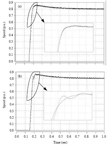 | |
| Fig. 10: | Motor runs at 0.8 p.u., solid line representing the real speed and dashed line denoting the estimated, (a) without feedback and (b) with introduced feedback gain |
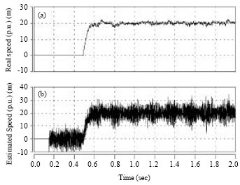
In order to test the noise sensitivity of proposed design, random noise is added to the sample current with the magnitude of 0.02 p.u. Figure 11a-c show the motor running at 0.02 p.u. It can be found that the unchanged proportional gain of controller makes the noise sensitivity almost the same in both cases.
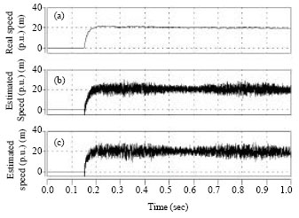 | |
| Fig. 11: | Motor runs at 0.02 p.u., (a) Real speed, (b) estimated speed without feedback and (c) estimated speed with introduced feedback, in sequence |
 | |
| Fig. 12: | Motor runs at 0.8 p.u., with the corner frequency of PI controller 800 rad sec-1 when feedback gain is zero. Solid line representing the real speed and dashed line denoting the estimated |
Meanwhile, the increased corner frequency can improve the steady state accuracy with the feedback gain design.
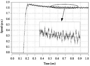
Figure 12 shows that when the feedback gain is zero, the corner frequency of estimation PI controller is design 800 instead of 160 rad sec-1, the estimated speed will oscillate dynamically and steadily. It is due to the reduced stability margin by the increased corner frequency, which is in good agreement with the analysis.
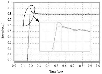 | |
| Fig. 13: | Motor runs at 0.8 p.u., with the natural frequency of control loop 100 rad sec-1 when feedback gain is zero. Solid line representing the real speed and dashed line denoting the estimated |
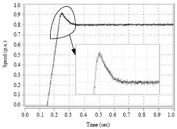 | |
| Fig. 14: | Motor runs at 0.8 p.u. full-loaded |
 | |
| Fig. 15: | (a, b) Motor runs at 0.02 p.u. full-loaded |
Figure 13 shows that when natural frequency of control loop is designed 100 rad sec-1, 5 times the preset design, the estimated speed will fall behind the real one and oscillation occurs in the estimated speed.
Figure 14, 15a and b show the motor speed, with estimated speed close-loop controlled. It can be seen that with the introduced feedback gain, speed estimation loop and control loop design, the estimated speed can follow well with the real one when the motor is full loaded in high and low speed range, respectively.
DISCUSSION
The proposed full order observer design in speed sensorless induction motor drive discusses the feedback gain and speed adaptive PI design. By observing the zeros and poles distribution of plant function and analyzing its bode diagram, the study finds that the feedback gain design will influence the characteristics of plant function and so the corresponding speed adaptive PI design have to be altered accordingly. That is to say, the two main parts have to be considered simultaneously. As is drawn in the study, the integral part of speed adaptive PI part determines the steady accuracy, while the proportional part influences the response speed and has relations with noise sensitivity. Meanwhile, the proportional and integral parts have to be in harmony to maintain the stability of estimation system due to the characteristics of plant function. The first simulation experiment demonstrates that with the introduced feedback gain design the integral part can be made larger to decrease the speed error and the oscillation in the transient disappears for the improvement of characteristic of plant function. The second one shows that with the introduce feedback gain design and zero feedback, respectively, the proportional part can keep the same. The unchanged proportional gain of controller makes the noise sensitivity almost the same in both cases. Compared with other full order observer feedback gain designs by Kubota et al. (1993), who proposed allocating the observer poles to be k times those of motor and Maes and Melkebeek (2000), who proposed shifting to left. Both of them were just from the point of observer state matrix stability and convergence, lacking in speed estimation loop influence consideration. The introduced feedback gain design is aimed at improving the zeros and poles distribution of plant function and therefore the characteristic improves too. It has benefit for the speed adaptive PI design. As for the observer discrete error effect (Hinkkanen and Luomi, 2001) and there exists an unstable region in full-order observer based speed sensorless system for its uncompleted speed adaptive law, the feedback gain design does not consider them and therefore the introduced design can not solve the problems mentioned above. Different from the speed PI design method by Suwankawin and Sangwongwanich (2006), who examines the ramp function response of plant function to determine the PI design, this study proposes designing PI according to the bandwidth of speed estimation loop and speed control loop. The harmony between the two loop must be maintained to ensure stability. It in total help design speed estimation PI and speed control PI, which is not mentioned in other literatures.
CONCLUSION
The design of full order observer in speed sensorless induction motor drive is the research target in this study. The characteristic of speed estimation plant function has the most important role in the estimation dynamic performance and stability. Based on the analysis of it, a simple and parameter independent feedback gain is introduced to improve the characteristics of plant function. Steady state accuracy, noise sensitivity, relation between the speed estimation loop and control loop determine the PI design. Motor can run well with the proposed method.
ACKNOWLEDGMENTS
This study was supported by the National Natural Science Foundation of China under Project 60874047 and Natural Science Foundation of Hubei Province under Project 2007ABA281.
REFERENCES
- Schauder, C., 1992. Adaptive speed identification for vector control of induction motors without rotational transducers. IEEE Trans. Ind. Appl., 28: 1054-1061.
CrossRefDirect Link - Cirrincione, M., M. Pucci, G. Cirrincione and G.A. Capolino, 2006. An adaptive speed observer based on a new total least square neuron for induction machine drives. IEEE Trans. Ind. Appl., 42: 89-104.
CrossRefDirect Link - Holtz, J. and J.T. Quan, 2003. Drift and parameter compensated flux estimator for persistent zero-stator-frequency operation of sensorless-controlled induction motors. IEEE Trans. Ind. Appl., 39: 1052-1060.
CrossRefDirect Link - Kubota, H., K. Matsuse and T. Nakano, 1993. DSP-based speed adaptive flux observer of induction motor. IEEE Trans. Ind. Appl., 29: 344-348.
CrossRefDirect Link - Cirrincione, M., M. Pucci, G. Cirrincione and G.A. Capolino, 2007. Sensorless control of induction motors by reduced order observer with MCA EXIN+ based adaptive speed estimation. IEEE Trans. Ind. Elect., 54: 150-166.
CrossRefDirect Link - Yan, Z., C. Jin and V.I. Utkin, 2000. Sensorless sliding-mode control of induction motors. IEEE Trans. Ind. Elect., 47: 1286-1297.
Direct Link - Kim, Y.R., S.K. Sul and M.H. Park, 1992. Speed sensorless field-oriented control of induction motor using extended Kalman filter. Proceedings of the IEEE Conference Record of the Industry Applications Society Annual Meeting, Oct. 4-9, Houston, TX, USA., pp: 594-599.
CrossRef - Ohtani, T., N. Takada and K. Tanaka, 1992. Vector control of induction motor without shaft encoder. IEEE Trans. Ind. Appl., 28: 157-164.
CrossRefDirect Link - Hinkkanen, M. and J. Luomi, 2001. Novel full-order flux observer structure for speed sensorless induction motors. Proceedings of the 27th Annual Conference of the IEEE Industrial Electronics Society, Nov. 29-Dec. 2, Denver, Co., USA., pp: 1333-1338.
CrossRef - Hinkkanen, M. and J. Luomi, 1998. Parameter sensitivity of full-order flux observer for induction motors. IEEE Trans. Ind. Appl., 39: 1127-1135.
CrossRefDirect Link - Suwankawin, S. and S. Sangwongwanich, 2006. Design strategy of an adaptive full-order observer for speed-sensorless induction-motor drives-tracking performance and stabilization. IEEE Trans. Ind. Elect., 53: 96-119.
CrossRefDirect Link - Harnefors, L. and M. Hinkkanen, 2008. Complete stability of reduced-order and full-order observers for sensorless IM drives. IEEE Trans. Ind. Elect., 55: 1319-1329.
CrossRefDirect Link - Suwankawin, S. and S. Sangwongwanich, 2002. A speed-sensorless IM drive with decoupling control and stability analysis of speed estimation. IEEE Trans. Ind. Elect., 49: 444-455.
CrossRefDirect Link - Hofmann, H. and S.R. Sanders, 1998. Speed-sensorless vector torque control of induction machines using a two-time-scale approach. IEEE Trans. Ind. Appl., 34: 169-177.
CrossRefDirect Link - Hinkkanen, M. and J. Luomi, 2004. Stabilization of regenerating-mode operation in sensorless induction motor drives by full-order flux observer design. IEEE Trans. Ind. Elect., 51: 1318-1328.
CrossRefDirect Link - Kubota, H., I. Sato, Y. Tamura, H. Ohta and Y. Hori, 2002. Regenerating-mode low-speed operation of sensorless induction motor drive with adaptive observer. IEEE Trans. Ind. Appl., 38: 1081-1086.
CrossRefDirect Link - Maes, J. and J.A. Melkebeek, 2000. Speed-sensorless direct torque control of induction motors using an adaptive flux observer. IEEE Trans. Ind. Appl., 36: 778-785.
CrossRefDirect Link - Yang, G. and T.H. Chin, 1993. Adaptive-speed identification scheme for a vector-controlled speed sensorless inverter-induction motor drive. IEEE Trans. Ind. Appl., 29: 820-825.
CrossRefDirect Link