
Chen Xu
School of Information and Control, Nanjing University of Information Science and Technology, 210044, China
Lin Guoyu
School of Information and Control, Nanjing University of Information Science and Technology, 210044, China
Information Technology Journal
Year: 2011 | Volume: 10 | Issue: 11 | Page No.: 2052-2059


ABSTRACT
This study discusses a semi-physical simulation platform for Adaptive Front lighting System (AFS) based on vehicle driving simulator. The research background, performance and development of AFS are introduced firstly. Then the architecture of AFS is proposed which includes three parts: vehicle sensors, control module and actuator unit. On the semi-physical simulation platform, the signals of gear, throttle pedal, clutch pedal, brake pedal and steering wheel are sampled by PC and with which the vehicle kinematics model is established. On the base of these, a genetic-based hybrid fuzzy-PID controller is proposed for coordinately controlling of AFS. This developed controller has capability to collect sensors data, send them into the algorithmic program and control front light up-down and left-right movement. The kinematics model and controller are tested on the semi-physical simulation platform and the results can be analyzed. This provides a convenient testing platform for control algorithm of AFS.
PDF Abstract XML References Citation
Received: June 28, 2011;
Accepted: August 11, 2011;
Published: September 23, 2011
How to cite this article
Chen Xu and Lin Guoyu, 2011. A Semi-physical Simulation Platform for Adaptive Front Lighting System (AFS). Information Technology Journal, 10: 2052-2059.
DOI: 10.3923/itj.2011.2052.2059
URL: https://scialert.net/abstract/?doi=itj.2011.2052.2059
DOI: 10.3923/itj.2011.2052.2059
URL: https://scialert.net/abstract/?doi=itj.2011.2052.2059
INTRODUCTION
Preventive and active safety of road vehicles is one of the top priorities in car design and development nowadays. Passive and active safety systems have been developed in research and development activities to produce vehicles that will perform at the highest level of safety and ensure comfortable driving under various conditions (Hacibekir et al., 2006). Moreover, researchers have been trying to develop preventive and active safety systems that will actively support driving safety using today's advanced electromechanical systems.
The major problem hindering safer and more comfortable driving is the driver’s limited reaction time in the presence of changing road conditions. An aim of development in active safety is to reduce the reaction time of the driver by improving visibility and thus achieve a significant increase in road safety and driving comfort. Alexander and Lunenfeld (1990) mentioned that driving an automobile is primarily a visual task because vision contributes as much as 90% of the information needed to drive. Good visibility contributes to driver confidence and enables more relaxed and safer driving. Moreover, statistics clearly show that the majority of accidents take place at night or in bad weather because of low visual conditions (Shadeed and Wallaschek, 2007). So under such conditions, it is of great importance to use available technology to contribute to road safety by improving the visual conditions provided by vehicle front lights.
Lighting in modern vehicles has been steadily improving in the last decades. Modern technology provides new light sources and more powerful optical systems. With current sensors and control equipment, advanced dynamic lighting systems are possible. The Adaptive Front lighting System (AFS) is the outcome of engineering efforts in developing the next generation lighting systems not only for drivers but also for all other road users. As the active-safety system, AFS has been paid more and more attention. Now R123 applied to Adaptive Front Lighting System (AFS) is issued by United Nations Economic Commission for Europe (Roslak and Wallaschek, 2004) and regulations are expected within years in our country.
AFS is an active-safety front lighting system which will enhance visibility at night by changing the light distribution according to the road and the driving condition (Hacibekir et al., 2006; Roslak and Wallaschek, 2004). In the horizontal plant, low beam of front light has ability to swivel horizontally which according to steering wheel angle and vehicle velocity; in the vertical plant, low beam front light can swivel vertically according to vehicle gradient which getting from horizontal sensor. Due to the automatically moveable light distribution depending on the environment, the range of low beam will be enlarged in curved roads and crossway. So AFS is most advanced vehicle lighting system which can make driver have more clear view when driving at night and have abundant time to deal with the emergency. Thereby the drive safety is improved greatly.
This study introduces a semi-physical simulation platform that visualizes the complex light characteristics of low beam of front light in detail and control in real-time on a PC-based system. When the user drives the vehicle simulator over a virtual test track at the night, all the information of gear, throttle pedal, clutch pedal, brake pedal and steering wheel can be collected by the vehicle simulator. Then by decision and calculation, the swivel angle of low beam of front light will be figured out. Later the swivel angle will be sent to actuator unit which drives two low beam light axes to the expectation position. Finally we will obtain the best illumination effect.
ARCHITECTURE OF AFS
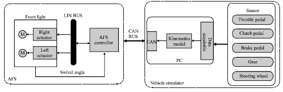
AFS includes three parts: collection module, AFS controller and actuator unit. Collection module samples all the signals of gear, throttle pedal, clutch pedal, brake pedal and steering wheel by sensors and data acquisition card; AFS controller manages all computing and controlling tasks; actuator unit drives front light axis to the aim position. In the following paragraphs, further definition of each part will be given and the architecture of AFS is shown in Fig. 1.
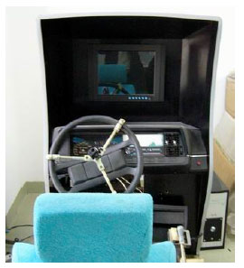
The vehicle simulator can provide the driver with a realistic interpretation of operating automobile, so AFS can be established in laboratory on the simulation platform. The vehicle simulator is composed of the following components: vehicle dynamic model (motion controller), visual scene, scenario editor, driving cab, sound device and hydraulic platform, shown in Fig. 2. The state parameters about the vehicle simulator which include steering wheel, gear, throttle pedal, clutch pedal, brake pedal, velocity and vehicle gradient collected by a special data acquisition card based on PCI. The collection module has CAN interface, through which all these information can be shared with AFS controller.
AFS controller is the key unit of the whole system. It gathers all sensors’ signals mentioned above, by decision and computing, it will “know” vehicle state in this moment. Based on AFS kinematics model and control strategy which will be discussed later, AFS controller figures out the control parameters. Then the control parameters will be sent to actuator unit. Then, AFS controller will start the next cycle.
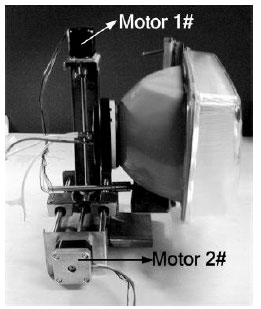
Actuator unit includes power drive circuit and DC motors. There are two DC motors and their drive circuit charge for low beam light axis moving on the vertical and horizontal plant. The schematic diagram of AFS mechanical structure is shown in Fig. 3. Drive circuit get control parameters from AFS controller and drive DC motor to the aim position. By means of closed loop position control, the system has high control precision.
KINEMATICS MODEL
AFS has ability to identify vehicle running state and adjust the low beam to the appropriate angle, making better illumination effect. At the same time, it’s important to take account of vehicle dynamic factors including vehicle velocity, steering wheel angle and vehicle body gradient to decide the low beam swivel angle. So AFS kinematics model should be established, through which the relationships among these factors must be present clearly.
Due to two freedom-degrees which AFS low beam has, kinematics model of system can be classified as two parts: the one is horizontal plant kinematics model and the other is vertical plant kinematics model. The further define of each part will be presented as follow.
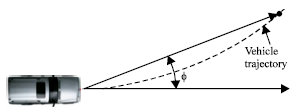
Horizontal plant kinematics model: The schematic of horizontal plant kinematics model is shown in Fig. 4. The output horizontal swivel angle φ which is according to the steering wheel angle and vehicle velocity, can be calculated by equation recommended by SAE (Society of Automotive Engineers) (BmbH, 2004a; BmbH, 2004b) as following:
| (1) |
 | |
| Fig. 1: | Architecture of AFS |
 | |
| Fig. 2: | Vehicle simulator |
 | |
| Fig. 3: | Schematic diagram of AFS mechanical structure |
This is an empirical formula, Where R is steering radius of vehicle, X is stopping distance and H is height of low beam to the ground. But it is very difficult to measure R. According to Ackermann steering geometry, R equals approximately to L/sinβ, where L is wheel base and β is outside wheel angle. Generally, β is directly proportional to steering wheel angle (The proportion of automobile is about 1:10).
 | |
| Fig. 4: | Horizontal plant kinematics model |
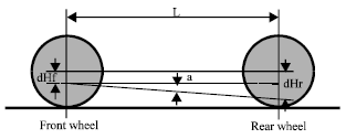 | |
| Fig. 5: | Vertical plant kinematics model |
Vertical plant kinematics model: For the vertical plant, swivel angle of low beam light axis is adjusted according to the gradient of vehicle. The schematic of vertical plant kinematics model is shown below in Fig. 5. Light axis vertical swivel angle output can be derived:
| (2) |
where, dHf is the variation of the front wheel height and dHr is the variation of the rear wheel height. From the schematic diagram, L is the wheelbase. Now we can see if dHf-dHr>0, the front light should swivel upward, otherwise downwards.
In this kinematics model, the input parameters include vehicle velocity, steering wheel angle and vehicle body gradient; the output parameters are light axis horizontal and vertical swivel angle. The basic relationship between them is reflected. It’s a basic kinematics model of AFS. But the real factors, such as the performances of cornering braking, the flexural rigidity of the wheel and the variation of load are all ignored. So the kinematics model should be modified by a great deal of experiment data.
AFS CONTROLLER
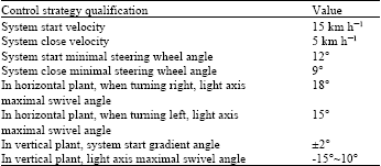
The AFS controller calculates the desired front light angle φ and α based on the state of the vehicle using kinematics model Eq. 1 and 2. The resulting desired front light angle is converted to a required number of steps and direction for a step motor or sent to a PID position control loop when a DC motor is used. DC motors were used in this study for adaptive tracking of curves by the front light. The control strategy qualification is shown below in Table 1.
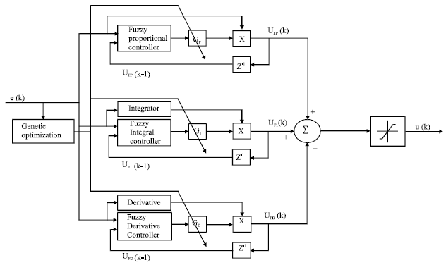 | |
| Fig. 6: | Block diagram of the proposed fuzzy-PID controller |
| Table 1: | Control strategy qualification |
 | |
Here, a genetic-based hybrid fuzzy-PID controller is developed which employs a fuzzy-PID controller integrating an industrial PID controller (Yu et al., 2009; Oh and Pedrycz, 2002). The fuzzy-PID controller consists of three independent fuzzy sub-controllers, namely, fuzzy-based proportional controller, fuzzy-based integral controller and fuzzy-based derivative controller. A genetic optimization technique (Oh et al., 2004) is used to determine the optimal values of the scaling factors of the output variables of these sub-controllers. These independent controllers are grouped together and integrated with an industrial PID controller to form a hybrid-fuzzy PID controller. Figure 6 shows the architecture of the proposed genetic-based hybrid fuzzy-PID controller. The hybrid fuzzy-PID controller is anticipated to accommodate the robust stabilization and disturbance rejection problems.
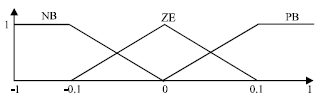
Fuzzy-based controller: The following provides the detailed design of the fuzzy-based proportional controller. The first step in designing the controller is to decide which state variables of the drives system can be taken as the input signals to the controller. Both the position error, e(k) and the delayed feedback control signal, UFP(k-1), are used as the inputs to the position controller. The output of the fuzzy-based proportional controllers is the gain, FKP. The linguistic fuzzy variable e(k) has three sets: Positive Large (PL), Zero (ZE) and Negative Large (NL), with each set having its own membership function. Furthermore, the linguistic fuzzy variable UFP(k-1)” has also three sets: Positive Large (PL), Zero (ZE) and Negative Large (NL), with each set having its own membership function. After specifying the fuzzy sets, it is required to determine the membership functions for these sets. Typical triangular membership functions are utilized for the e(k) and UFP(k-1). Figure 7 and 8 show the membership functions for the fuzzy inputs. The three fuzzy sets can be symbolized by Fi j, I = 1, 2 and j = 1, 2, 3. Their corresponding membership functions can be symbolized by μF j (e(k), UFP(k-1)), j = 1, 2, 3.
The next step in the design of the fuzzy sub-controller is the determination of the fuzzy IF-THEN inference rules. The number of fuzzy rules that are required is equal to the product of the number of fuzzy sets that make up each of the two fuzzy input variables. Thus, a total of 9 fuzzy rules are required. In general, a typical fuzzy rule is of the form:
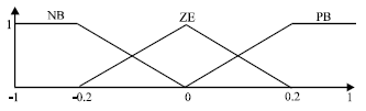 | |
| Fig. 7: | Membership functions for e(k) |
 | |
| Fig. 8: | Membership functions for UFP(k-1) |
The conjunction of the rule antecedents is evaluated by the fuzzy operation intersection which is implemented by the min operator. The rule strength represents the degree of membership of the output variable for a particular rule. Defining the rule strength, ξi,j of a particular rule as:
| (3) |
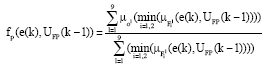
where, iε[PL, ZE, NL] is associated with the fuzzy variable, e(k) and jε[PL, ZE, NL] is associated with the fuzzy variable, UFP(k-1). The fuzzy inference engine uses the appropriately designed knowledge base to evaluate the fuzzy rules and produce an output for each rule. Subsequently, the multiple outputs are transformed to a crisp output by the defuzzification interface. Once the aggregated fuzzy set representing the fuzzy output variable has been determined, an actual crisp control decision must be made. The process of decoding the output to produce an actual value for the controller gain FKP is referred to as defuzzification. Thus, a fuzzy logic controller-based center-average defuzzifier is implemented. The output of fuzzy-based proportional controller is given by:
| (4) |
where,
 | (5) |
The linguistic fuzzy output variable FKP has nine sets: Negative Very Large (NVL), Negative Large (NL), Negative Medium (NM), Negative Small (NS), zero, Positive Small (PS), Positive Medium (PM), Positive Large(PL) and Positive Very Large (PVL).
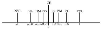 | |
| Fig. 9: | Membership functions (singlectons) for FKP |
The two fuzzy sets, namely, Negative Very Large (NVL) and Positive Very Large (PVL) are added to enhance the tracking performance. After specifying the fuzzy sets, it is required to determine the membership functions for these sets μ0l for l = 1... 9. The membership function for the fuzzy set-representing zero is a fuzzy singleton. Additionally, the other membership functions are composed of fuzzy singletons within the region defined for the fuzzy output variable. Figure 9 shows the resulting membership functions for the variable FKP.
Consequently, the control signal generated by the fuzzy-proportional controller can be written as follows:
| (6) |
where, GP is the scaling factor that tuned experimentally using genetic optimization.
The fuzzy-based integral controller and fuzzy-based derivative controller are desinged using the same method. Finally, the overall output of fuzzy-PID was derived as follows:
| (7) |
where, UFI(k) and UFD(k) are the fuzzy variable just as UFP(k). Saturation is also incorporated in the fuzzy-PID controller structure. As such, the final output of proposed controller is:
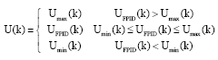 | (8) |
where, Umin and Umax are the permitted minimum and maximum inputs to the drive system.
Genetic optimization: Genetic optimization-based approach is used to ensure the best performance of the proposed fuzzy-PID controller. The genetic optimization imitates the natural evolution process in which the fittest survive and the best genes are propagated to the next generation. A population of chromosomes is evaluated and a fitness value is assigned to each.
 | |
| Fig. 10: | Functional block diagram showing the genetic optimization process |
Each chromosome represents a possible solution for a given problem and the ones with the higher fitness have a better chance to reproduce. One of the main features is that it could work well for nondeterministic systems, ill defined systems and systems that are hard to model (Seng et al., 1999). Furthermore, the final performance outcome of the algorithm does not depend highly on the initial choice of chromosomes. When the genetic optimization is applied to control applications each chromosome represents the set of controller’s adjustable parameters and the fitness value is a quantitative measure of the controller performance. The autotuning consists of the automatic adjustment of these parameters to optimize the controller performance. The genetic optimization combines a stochastic exploratory search with a well defined cost function to find the solution that fit the problem the best. The cost function that represents the fuzzy-PID controller is defined as follows:
| (9) |
where, GP, GI, GD, are the output scaling factors of the fuzzy-PID sub-controllers. The function f represents the relationship between the overall performance and the design parameters. The ptimization problem for the fuzzy-PID controller is described as (Farag et al., 1998):
| (10) |
where, F is the fitness function. There are various ways to calculate the overall performance J of the controller but for simplicity reasons the Mean Square Error (MSE) performance index was selected,
| (11) |
where, N is the length of the evaluation window and e(k) is the error between the reference position and the actual position. The fitness of each parameter set, or chromosome can be determined as follows:
| (12) |
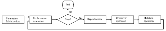
Once the fitness function is established, the genetic operators and parameters are defined. The genetic optimization consists of three basic operators: the crossover, mutation and reproduction. The parameters are the number of generations, the population size, the probability of crossover and mutation. In general, an initial population size is defined and evaluated with the fitness function. Once each chromosome has a fitness assigned to it, the reproduction process takes place with those that are more fit having a greater chance to be selected. Then, each of the two operators of crossover and mutation are applied to create the new pool of chromosomes to be evaluated. Crossover occurs when the chromosomes partially exchange their information by interchanging some of their genes. Mutation is the random alteration of a particular section of the chromosome by occasionally changing one of more of the genes that are part of the chromosome. Figure 10 is the functional block diagram showing the procedure of the genetic optimization.
The overall geneticbased auto-tuning procedure of the fuzzy-PID controller consists of the following steps:
| Step 1: | Select the control topology of the Fuzzy-PID controller in which the outputs of the sub-controllers are used as the FPID gains |
| Step 2: | Define the characteristics of the fuzzy-PID subcontrollers such as number of fuzzy sets, membership functions, fuzzy rules and defuzzyfication method |
| Step 3: | Set the genetic optimization parameters, such as the number of generations, the population size, the probability of crossover and mutation |
| Step 4: | Tune of the parameters, GP, GI and GD of the Fuzzy-PID controller using the genetic optimization procedure |
EXPERIMENTS
According to the architecture of AFS, the whole system has been established in our laboratory.
| Table 2: | Left light horizental plant data |
 | |
An ultimate goal of the system is to verify the control strategy and we present an experimental analysis conducted on this semi-physical simulation platform. The software of the host computer is developed by Delphi language, including data cellection, calculation, display and data transmission based on LIN bus, shown in Fig. 11.
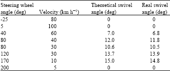
Horizontal plant experiment: According to horizontal plant kinematics model, we measured real swivel angle and made contrast to theoretical swivel angle when given input data. Details are presented in Table 2 and Table 3. Steering wheel turn-left angle is defined positive. By contraries, turn-right angle is negative.
From the experimental data we can see:
| • | When the steering wheel turns right, the left front light should keep the original position. So the theoretical swivel angle and the real swivel angle of left front light is 0°. In the same way, when the steering wheel turns left, the theoretical swivel angle and the real swivel angle of right front light is 0° |
| • | When the velocity below 5 km h-1 or the steering wheel angle below 9°, the front light axis will not move |
| • | The right and left maximal swivel angle in horizontal plant are different, the right can reach 18° and the left can reach 15° |
| • | The maximum error of swivel angle is 0.2° which meets the accuracy requirements |
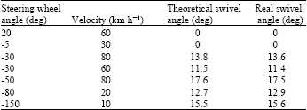
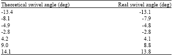
Vertical plant experiment: Just like horizontal plant, some input data been given, we measured real swivel angle and made contrast with theoretical swivel angle. Details are presented in Table 4.
The experimental data shows us that:
| • | The maximal swivel angle in vertical plant can reach -13~14° |
| • | The maximum error of swivel angle is 0.3° which satisfies our application requirement completely |
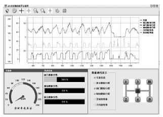 | |
| Fig. 11: | Software interface on semi-physical simulation platform |
| Table 3: | Right light horizental plant data |
 | |
| Table 4: | Vertical plant data |
 | |
CONCLUSION
The semi-physical simulation platform for Adaptive Front lighting System (AFS) based on vehicle driving simulator was disccussed in this study. It can be used for system-level research, especially for control algorithm design. The simulation results indicate that the design mentioned in the study can be conveniently appllied to adapt light distribution according to the changes in the traffic conditions and to achieve an optimal illumination of the traffic space. The experiments verified the semi-physical simulation platform available and effective.
ACKNOWLEDGMENT
This research is sponsored by Science and Research Program of SuZhou (No.SG0956) and the fund of Nanjing University of Information Science and Technology (No.20080307, No.20090212).
REFERENCES
- Hacibekir, T., S. Karaman, E. Kural, E.S. Ozturk, M. Demirci and B.A. Guvenc, 2006. Adaptive headlight system design using hardware-in-the-loop simulation. Proceedings of the IEEE International Symposium on Intelligent Control, Computer Aided Control System Design, Oct. 4-6, Munich, pp: 915-920.
CrossRef - Shadeed, F.H. and S.J. Wallaschek, 2007. Concept of an intelligent adaptive vehicle front-lighting assistance system. Proceedings of Intelligent Vehicle Symposium, June 13-15, Istanbul, pp: 1118-1121.
CrossRef - Roslak, J. and J. Wallaschek, 2004. Active lighting systems for improved road safety. Proceedings of Intelligent Vehicle Symposium, June 14-17, IEEE Xpore, pp: 682-685.
CrossRef - Yu, J., X. Hu and R. Ding, 2009. Fuzzy logic PID based control design for permanent magnet synchronous motor servo system. Proceedings of the 2nd International Conference on Intelligent Computation Technology and Automation, Oct. 10-11, Changsha, Hunan, pp: 728-731.
CrossRef - Oh, S.K. and W. Pedrycz, 2002. The design of hybrid fuzzy controllers based on genetic algorithms and estimation techniques. Kybernetes, 31: 909-917.
CrossRef - Oh, S.K., S.B. Rho and H.K. Kim, 2004. Fuzzy controller design by means of genetic optimization and NFN-based estimation technique. Int. J. Control Autom. Syst., 2: 362-373.
Direct Link - Seng, T.L., M.B. Khalid and R. Yusof, 1999. Tuning of a neuro-fuzzy controller by genetic algorithm. IEEE Trans. Syst. Man Cybern. Part B, 29: 226-236.
CrossRef - Farag, W.A., V.H. Quintana and G. Lambert-Torres, 1998. A genetic-based neuro-fuzzy approach for modeling and control of dynamical systems. IEEE Trans. Neural Networks, 9: 756-767.
CrossRef