
Guozhi Zhang
Mechanical and Electrical Engineering College, Xinxiang University, Xinxiang, 453000, China
Information Technology Journal
Year: 2013 | Volume: 12 | Issue: 13 | Page No.: 2547-2553


ABSTRACT
The computing method in a joint fastener with bolts was studied. The cooling method, pretension element method and tightening method used in the simulation were analyzed for their computing principle and application situation. The device with thread was analyzed with above three methods and their results were compared so as to give the simplifying criteria of joint surfaces. Furthermore, a joint of pipe and joint mechanical structure were analyzed with the pretension element method and their analysis results were obtained when the bolts were pretended and other loads were applied.
PDF Abstract XML References Citation
Received: May 20, 2013;
Accepted: July 22, 2013;
Published: September 21, 2013
How to cite this article
Guozhi Zhang, 2013. Study on Computing Method in a Joint Fastener with Bolts. Information Technology Journal, 12: 2547-2553.
DOI: 10.3923/itj.2013.2547.2553
URL: https://scialert.net/abstract/?doi=itj.2013.2547.2553
DOI: 10.3923/itj.2013.2547.2553
URL: https://scialert.net/abstract/?doi=itj.2013.2547.2553
INTRODUCTION
In engineering computation, there are a lot of joint surfaces with bolts which is the most widely used in mechanical structures. And thread connections can be divided into cylinder thread connection and taper thread connection (Yan, 1995). With rapid developments of advanced manufacturing technology (Xue et al., 2002; Williams, 2001; Yongwu et al., 2007) and modern design methods, people paid attention to design and manufacturing accuracy. Traditional design methods rely mainly on experience to design with the safety factor approach and make using materials redundancy or lack so as to lead to materials waste and fracture or other faults because of lack of strength (Byung-Young et al., 2004). Simulation computation for and taper thread connection is studied in oil machinery and helix angle is considered in finite element analysis taper thread and its 2D analysis was done (Guozhi et al., 2008; Xi et al., 2000; Chen and Deng, 2011; Xianyue et al., 2012). In heavy machinery, reliability analysis for connective bolt was done (Zhichao et al., 2002; Zongbao et al., 2012). In engineering applications, usually in the design and testing, tightening torque are usually applied for the cylindrical thread, there are more mature theoretical formula to calculate pretension force. Many simulation methods are based on this principle, such as cooling method and pretension element method. In two methods, the contact between threads is ignored, so, computation results are inaccurate and computation efficiency is very high. Moreover, effects of the preload are only reflected and contact stress can’t be obtained. The third method is tightening method, in which practical pretension process is simulated. In engineering computation, applicable simulation method for joint fastener with bolts is adopted according to analysis purpose. In the study in the manuscript, above three methods are discussed systematically and deeply and a joint of pipe was analyzed.
COMPUTING PRINCIPLE IN A JOINT FASTENER WITH BOLTS
Simulation methods of joint fastener with bolts are cooling method, pretension element method and tightening method but computing principle and scale of above three methods are different. The effects of preload to the parts with above three methods can be obtained. Here, above three methods are described briefly.
Cooling method: Based on expansion and contraction for heating and cooling, the bolt is assumed that it is cooled to make it shrink so as to result in the preload. Temperature load imposed is computed based on Hooke's Law and the preload. Because the contact between threads is ignored, computation results are inaccurate. But computation efficiency is very high. Moreover, with this method, effects of the preload is only reflected. However, when other loads need be imposed after preloads of all bolts are imposed and all bolts are locked, this method can’t be used.
Pretension element method: In ANSYS, a convenient method is provided and this method is pretension element method with PRETS179 element. PRETS179 element is as shown in Fig. 1. In Fig. 1, I and J are end nodes which are usually coincide and K is preload node which has only one degree of freedom. The bolt pretension structure is as shown in Fig. 2.
The pretension process in practice and ANSYS are as follows:
| • | The pretension process in practice the nut is tightened to reduce effective length of the bolt so as to make the bolt pretened. When desired preload is achieved and the wrench is removed, effective length of the bolt is unchanged |
| • | The pretension process in ANSYS. In the first load step, the preload is imposed. In the second load step, bolts are locked. In the third load step, other loads are applied |
Pretension element features are as follows:
| • | A group of preloaded element is defined as a “section” |
| • | Two dimensional or three dimensional line element connects two halves of the bolt together like hooks |
| • | The pretension load direction is constant which is not updated because of its rotation |
| • | There is no material properties or key option in the preloaded element |
| • | The matrix bolt element can be low order or higher order element of solid, shell and beam element |
| • | The preloaded element will automatically create in ANSYS if preloaded section is defined (ANSYS, 2000) |
 | |
| Fig. 1: | PRETS 179 element model of the preload bolt in FEA |
Tightening method: According to the pretension process in practice, in ANSYS, tangential force is computed based on tightening movement and imposed on the nut. Tightening device is as shown in Fig. 3. In this method, the contact between threads and helix angle are considered, so this analysis is attached to non-linear analysis. Thus, computation scale is very large and computation efficiency is very low. Thus, computation results are accurate and local contact stress can be obtained.
SIMPLIFYING METHOD OF JOINT SURFACES
In complex mechanical equipments or mechanical structures, there are a lot of joint surface structures so as to exist more nonlinear contact surfaces. So, when whole machines or whole structures are computed, the contact don’t considered and joint surfaces with bolts simplified generally as the whole part so as to make local stiffness increase. While all contacts are considered so as to make computing scale increase and computation not converged. Thus, when contact problems are solved, reasonable simplifications must be done. Combining with specific analysis purpose and paying attention to simplification principles so as to avoid obtaining inaccurate results because of improper assumptions. Basic computing scheme is as shown in Fig. 4.
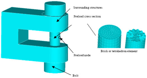 | |
| Fig. 2: | Preload cross section of the bolt pretension structure in FEA |
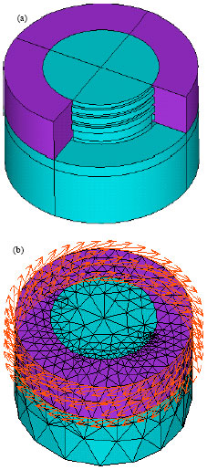 | |
| Fig. 3(a-b): | 3D model and finite element model of the tightening device (a) 3D model and (b) Finite element model |
 | |
| Fig. 4: | Simplifying computing scheme of joint surfaces in mechanical structures |
RESULTS COMPARISON OF DIFFERENT COMPUTING METHODS FOR A JOINT FASTENER WITH BOLTS
With cooling method and pretension element method, tightening device was computed, its 1/4 finite element models because of symmetry of load, constraint conditions and geometry are established and as shown in Fig. 5 and equivalent stress distribution are as shown in Fig. 6. With tightening method, it is computed and results are as shown in Fig. 7. From Fig. 7a, maximum equivalent stress is in the root of the first lap thread which is attached to engineering practice and the difference of the preload between FEA (Finite Element Analysis) results with tightening method and theoretical results based on mechanical design is only 3%. Comparing with Fig. 6 and 7, stress distribution of cooling method and pretension element method are similar and maximum error between them is 11%, because temperature load imposed in method was estimated based on simple theoretical model.
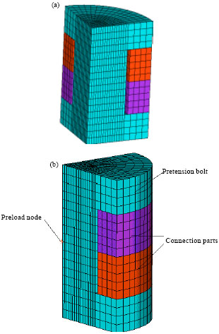 | |
| Fig. 5(a-b): | Finite element model of a joint fastener with a bolt (a) With cooling method and (b) With pretension element method |
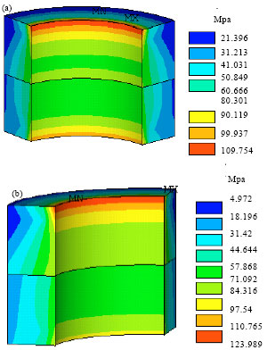 | |
| Fig. 6(a-b): | FEA results of a joint fastener with a bolt (a) With cooling method and (b) With pretension element method |
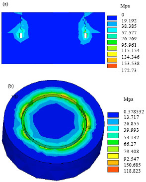 | |
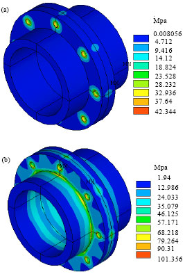
| Fig. 7(a-b): | FEA results with tightening method (a) Equivalent stress distribution in contact area and (b) Equivalent stress distribution in joint area |
While, differences between tightening method and other computation methods are obvious, because the contact between threads and helix angle are considered. However, stress distribution in joint area is similar.
ANALYSIS OF TYPICAL APPLICATION EXAMPLE
Example 1: A joint of pipe was computed. There are 10 bolts in joint areas and finite element model with preload element method is as shown in Fig. 8. There are two load steps. In the first load step, preloads of 10 bolts are imposed. In the second load step, 10 bolts are locked and uniform tensile force is imposed in the other end of the pipe joints. Its FEA results are as shown in Fig. 9.
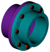 | |
| Fig. 8: | Finite element model of a joint of pipe |
 | |
| Fig. 9(a-b): | FEA results of a joint of pipe (a) First load step and (b) Second load step |
Because effects of the preload is only considered, pretension element method is used. From Fig. 9, the preload is appropriate and it works well.
Example 2
Theoretical estimating model: Joint parts in complex mechanical structures are simplified as proper simple model which is as shown in Fig. 10. Through the model, estimate the state of joint surfaces and judge whether joint surfaces can be binded so as to bear loads. If joint surfaces can be binded, two parts can be added to a part with ignoring local stress when overall complex mechanical structures are analyzed. Otherwise, nonlinear contact between two parts must be considered.
Through deducing, theoretical estimating model is:
| (1) |
where, a is the distance between the center of top bolts and the center of bottom bolts; F is the load; L2 is the length of second part; N1 is the number of top bolts; F’yj is minimum preload to make joint surfaces bind.
 | |
| Fig. 10: | Simple model of joint parts in complex mechanical equipments |
If imposing preloads Fyj is more than minimum preload F’yj that is Fyj≥F’YJ, two parts can be added to a part with ignoring local stress when overall complex mechanical structures are analyzed. If Fyj<F’yj, nonlinear contact between two pars must be considered.
The structure of Fig. 10 is computed. Where, F = 300 N, L = 100 mm, L2 = 500 mm, a = 40 mm, N1 = 2. Its 1/2 finite element model was established because of its symmetry of structure, loads and constraint conditions and its finite element model is as shown in Fig. 11. In finite element analysis, pretension element method is used. Compute with two load steps, preloads of bolts are imposed in the first load step, lengths of bolts are locked in the second load step.
Different preloads: Bolt diameters d = 4 mm, imposing preloads are 310, 500, 1000 and 3400 N. Based on Eq. 1, F’yj = 3333 N. When imposing preload is 3400 N, imposing preload is more than minimum preload. The computing results are as shown in Fig. 12. In Fig. 12, when Fyj = 0 N, two parts are added to a part. From Fig. 12a, when imposing preloads increase, the changing range of maximum equivalent stress (σmax) of its fixed end is very small and 0.003 Mpa because of joint parts and the bolts can transform loads. From Fig. 12b, maximum flection (ymax) of its end decrease with imposing preloads increasing, the contact surfaces can’t be binded so as to make its flection get maximum value. Moreover, when imposing preload is 310 N which makes the second part not decline because of its second part gravity, its maximum flection increase by 0.724 mm than computing result of a part.
 | |
| Fig. 11(a-b): | Finite element model of simple model of joint parts (a) Overall finite element model and (b) Local finite element model in the joint surfaces |
 | |
| Fig. 12(a-b): | Finite element computing results of different preloads (a) The curve of max. equivalent stress with preloads and (b) The curve of max. flection with preloads |
From above analysis results, imposing preloads can significantly affects to its local stress in joint parts and maximum flection of its end while imposing preloads can’t affects load transmission of bolts.
Different diameters: Imposing preload is 310 N and bolt diameters are 3.5, 3 and 2.5 mm. The computing results are as shown in Fig. 13. In Fig. 13, when d = 0 mm , two parts are added to a part. From Fig. 13a, when bolt diameters increase, the changing range of maximum equivalent stress of its fixed end is very small and 0.003 Mpa because of joint parts and the bolts can transform loads. From Fig. 13b, maximum flection of its end decrease with bolt diameters increasing and bolt diameters can affect to contact state between surfaces and maximum flection of its end. Moreover, when bolt diameter is 2.5 mm, its maximum flection increase by 1.396 mm than computing result of a part. From above analysis results, when imposing preload is smaller, bolt diameters can significantly affects to contact state between surfaces and can’t affects load transmission of bolts.
 | |
| Fig. 13(a-b): | Finite element computing results of different diameters (a) Curve of max. equivalent stress with diameters and (b) Curve of max. flection with diameters |
Simplifying criteria of joint surfaces: Based on the above analysis results, simplifying criteria of joint surfaces of overall mechanical structures in FEM computation and procedures are summarized as follows:
| • | Determine purposes of analysis. If intensity of overall structuring is analyzed, non-linear contact of joint surfaces can be ignored. If deformation of overall structuring is analyzed, preloads and bolt diameters should be considered |
| • | Simplify the model and estimate. Through computing for joint structures of overall mechanical structures, determine influence of preloads and bolt diameters to overall structures and determine simplifying methods for joint surfaces |
| • | Establish simplifying models for joint structures. If local non-linear effects aren’t considered, add two joint parts into a part. Otherwise, nonlinear contact surfaces between two pars are established |
| • | Establish efficient and accurate non-linear finite element model. Based on computing results, evaluate the accuracy of results and determine the safety factor. That is to give a proper security domain |
CONCLUSION
Through typical tightening device, cooling method, pretension element method and tightening method used in the simulation were analyzed for their computing principle and application situation. From analysis results, when effects of the preload are considered and there are other loads, pretension element method is most applicable. Moreover, a joint of pipe and joint mechanical structure were computed with pretension element method and the preload is appropriate and it works well based on analysis results. Study of the paper supplies important reference value for simulation analysis of joint fastener with bolts in complex mechanical structures.
ACKNOWLEDGMENTS
This study was financially supported by the Natural Science Foundation of Henan Province (2011C460002) and Innovation Foundation of Xinxiang University (12ZB06).
REFERENCES
- Xue, Z., M.T.A. Saif and H. Yonggang, 2002. The strain gradient effect in microelectromechanical systems (MEMS). J. Microelectro. Mech. Syst., 11: 27-35.
CrossRefDirect Link - Williams, J.A., 2001. Friction and wear of rotating pivots in MEMS and other small scale devices. Wear, 251: 965-972.
CrossRefDirect Link - Xi, J., G. Nie, X. Mei and X. Wu, 2000. Influence of pitch error on loaded casing thread joints. J. Xian Jiaotong Univ., 34: 46-49.
Direct Link - Chen, L. and M. Deng, 2011. Study on algorithm of statistics for bolts information of steel bridge and iron tower based on assembly feature. Adv. Inform. Sci. Ser. Sci., 3: 1-11.
Direct Link